Pioneer DEH-1300MP Owner's Manual - Page 7
Installation
 |
UPC - 884938116442
View all Pioneer DEH-1300MP manuals
Add to My Manuals
Save this manual to your list of manuals |
Page 7 highlights
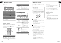
Section 03 Installation ! The semiconductor laser will be damaged if it overheats. Install this unit away from hot places such as near the heater outlet. ! Optimum performance is obtained when the unit is installed at an angle of less than 60°. 4 60° 5 1 2 3 DIN front/rear mount This unit can be properly installed using either front-mount or rear-mount installation. DIN Front-mount 1 Insert the mounting sleeve into the dashboard. For installation in shallow spaces, use the supplied mounting sleeve. If there is enough space, use the mounting sleeve that came with the vehicle. 2 Secure the mounting sleeve by using a screwdriver to bend the metal tabs (90°) into place. 1 1 Nut 2 Firewall or metal support 3 Metal strap 4 Screw 5 Screw (M4 × 8) # Make sure that the unit is installed securely in place. An unstable installation may cause skipping or other malfunctions. DIN Rear-mount 1 Determine the appropriate position where the holes on the bracket and the side of the unit match. 2 Tighten two screws on each side. 2 1 3 1 Dashboard 2 Mounting sleeve 3 Install the unit as illustrated. Use commercially available parts when installing. 2 1 Screw 2 Mounting bracket 3 Dashboard or console Use either truss (5 mm × 8 mm) or flush surface (5 mm × 9 mm) screws, depending on the bracket screw holes. Installation Removing the unit 1 Remove the trim ring. Section 03 Securing the front panel The front panel can be secured with the supplied screw. English 1 1 Trim ring 2 Notched tab ! Releasing the front panel allows easier ac- cess to the trim ring. ! When reattaching the trim ring, point the side with the notched tab down. 2 Insert the supplied extraction keys into both sides of the unit until they click into place. 3 Pull the unit out of the dashboard. 1 Screw Removing and re-attaching the front panel You can remove the front panel to protect your unit from theft. Press the detach button and push the front panel upward and pull it toward you. For details, refer to Removing the front panel to protect your unit from theft and Re-attaching the front panel on page 6. 12 En En 13
-
 1
1 -
 2
2 -
 3
3 -
 4
4 -
 5
5 -
 6
6 -
 7
7 -
 8
8 -
 9
9 -
 10
10 -
 11
11 -
 12
12 -
13
-
14
-
15
-
16
-
17
-
18
-
19
-
20
-
21
-
22
-
23
-
24
-
25
-
26
-
27
 |
 |
