Pioneer DEH-5400BT Service Manual - Page 17
Diagnosis, 5.1 Operational Flowchart
 |
View all Pioneer DEH-5400BT manuals
Add to My Manuals
Save this manual to your list of manuals |
Page 17 highlights
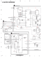
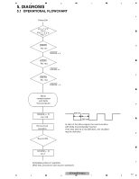
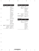
5 6 7 5. DIAGNOSIS 5.1 OPERATIONAL FLOWCHART Power ON Vcc = 1.2 V Pin 5 PVcc = 3.3 V Pin 1 BSENS Pin 141 BSENS = L ASENS Pin 143 ASENS = L DSENS Pin 140 DSENS = L Starts communication with Grille microcomputer. SWVDD
-
 1
1 -
2
-
3
-
4
-
5
-
6
-
7
-
8
-
9
-
10
-
11
-
 12
12 -
 13
13 -
 14
14 -
 15
15 -
 16
16 -
 17
17 -
 18
18 -
 19
19 -
 20
20 -
 21
21 -
 22
22 -
23
-
24
-
25
-
26
-
27
-
28
-
29
-
30
-
31
-
32
-
33
-
34
-
35
-
36
-
37
-
38
-
39
-
40
-
41
-
42
-
43
-
44
-
45
-
46
-
47
-
48
-
49
-
50
-
51
-
52
-
53
-
54
-
55
-
56
-
57
-
58
-
59
-
60
-
61
-
62
-
63
-
64
-
65
-
66
-
67
-
68
-
69
-
70
-
71
-
72
-
73
-
74
 |
 |

DEH-64BT/XNUC
17
5
6
7
8
5
6
7
8
C
D
F
A
B
E
5. DIAGNOSIS
5.1
OPERATIONAL FLOWCHART
Vcc = 1.2 V
Pin 5
PVcc = 3.3 V
Pin 1
BSENS
Pin 141
ASENS
Pin 143
DSENS
Pin 140
BSENS = L
DSENS = L
Starts
communication
with Grille
microcomputer.
SWVDD <- H
Pin 128
Source keys
operative
Source ON
SYSPW <- H
Pin 7
300 ms
300 ms
In case of the above signal, the communication
with Grille microcomputer may fail.
If the time interval is not 300 msec, the oscillator
may be defective.
Completes power-on operation.
(After that, proceed to each source operation)
Power ON
ASENS = L