Pioneer DEH-5400BT Service Manual - Page 29
How to remove the PU unit - installation
 |
View all Pioneer DEH-5400BT manuals
Add to My Manuals
Save this manual to your list of manuals |
Page 29 highlights
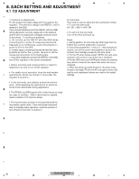
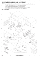
5 6 7 8 How to remove the PU unit 1. Create an empty-clamp state according to "How to create empty clamp state (motor drive)". 2. Hook the feeding screw biasing spring to a tentative hooking portion (Fig 2b). Be careful not to get injured by the A spring edge. 3. Hold the PU at the position A as shown in Fig 1. Slide the PU as far as possible toward the holder in the feeding screw so that a joint on the outer end of the feeding screw is loosened. 4. As shown in Fig 3, move the rear end of the feeding screw laterally and then upward, to remove it from the outer holder. 5. Lift the PU unit to disengage it from Part B of the chassis (Fig 4), and remove the PU unit. (Cautions) When re-installing the PU, be sure to first nip the chassis and the PU unit (Fig 4) at the position B. Also, make sure to fully hook the feeding screw biasing spring (Fig 2a). Please follow the service manual for adjustment of the PU unit after the re-installation. Slide toward inner circumference Fig 2a Fig 2b B Fig 1 B Fig 3 A Fig 4 Fully-hooked state Tentatively-hooked state C The spring is below a resin flange and is built inside the sheet metal bending. Outer holder Rear end of feeding screw Normal built-in state D [Incorrect built-in state] The chassis is not nipped between the PU case and the PU rack. E F 5 DEH-64BT/XNUC 6 7 8 29
-
 1
1 -
2
-
3
-
4
-
5
-
6
-
7
-
8
-
9
-
10
-
11
-
12
-
13
-
14
-
15
-
16
-
17
-
18
-
19
-
20
-
21
-
22
-
23
-
 24
24 -
 25
25 -
 26
26 -
 27
27 -
 28
28 -
 29
29 -
 30
30 -
 31
31 -
 32
32 -
 33
33 -
 34
34 -
35
-
36
-
37
-
38
-
39
-
40
-
41
-
42
-
43
-
44
-
45
-
46
-
47
-
48
-
49
-
50
-
51
-
52
-
53
-
54
-
55
-
56
-
57
-
58
-
59
-
60
-
61
-
62
-
63
-
64
-
65
-
66
-
67
-
68
-
69
-
70
-
71
-
72
-
73
-
74
 |
 |
