Pioneer DEH-5400BT Service Manual - Page 23
CD TEST MODE, Flow Chart
 |
View all Pioneer DEH-5400BT manuals
Add to My Manuals
Save this manual to your list of manuals |
Page 23 highlights
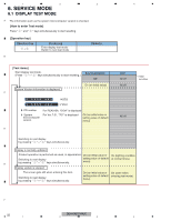
5 6 7 8 6.2 CD TEST MODE - Flow Chart A [4]+[6]->BUP+ACC ON Test Mode IN [CD] or [SOURCE] Source ON [Key] Contents TRK MIN Display [BAND] Power On (T.Offset is adjusted) TRK MIN SEC 00 00 00 [2] RF AMP *1 Gain switching TRK MIN SEC GG GG GG [BAND] [3] [6] [1] [>] [] CRG + 8X 8X 8X or 9X 9X 9X [] CRG/TR Jump + *4 TRK MIN SEC ?tr ?min ?sec [] CRG + / TR Jump + (Direction of the external surface) *2) Focus Close t S. Curve t F EQ measurement setting [
-
 1
1 -
2
-
3
-
4
-
5
-
6
-
7
-
8
-
9
-
10
-
11
-
12
-
13
-
14
-
15
-
16
-
17
-
 18
18 -
 19
19 -
 20
20 -
 21
21 -
 22
22 -
 23
23 -
 24
24 -
 25
25 -
 26
26 -
 27
27 -
 28
28 -
29
-
30
-
31
-
32
-
33
-
34
-
35
-
36
-
37
-
38
-
39
-
40
-
41
-
42
-
43
-
44
-
45
-
46
-
47
-
48
-
49
-
50
-
51
-
52
-
53
-
54
-
55
-
56
-
57
-
58
-
59
-
60
-
61
-
62
-
63
-
64
-
65
-
66
-
67
-
68
-
69
-
70
-
71
-
72
-
73
-
74
 |
 |

DEH-64BT/XNUC
23
5
6
7
8
5
6
7
8
C
D
F
A
B
E
6.2
CD TEST MODE
[Key]
Contents
Display
[BAND]
Power On
(T.Offset is adjusted)
TRK
MIN
SEC
00
00
00
[2]
RF AMP
Gain switching
GG
GG
GG
*1
[3]
Focus Close
S curve check
TRK
MIN
SEC
91
91
91
[6]
Focus Mode switching
0X
0X
0X
*2
[1]
Tracking Servo
Close
00
00
00
or 99
99
99
[>]
CRG +
[2]
Self-adjusting
switching
TRK
MIN
SEC
??
??
??
*3
*6
[<]
CRG -
*6
[BAND]
Power Off
TRK
MIN
SEC
[BAND]
Power Off
TRK
MIN
SEC
[BAND]
Power Off
TRK
MIN
SEC
[BAND]
Power Off
TRK
MIN
SEC
[1]
T.Close & AGC
Applicable servomechanism
TRK
MIN
SEC
?tr
?min ?sec
[3]
RF AGC /
RF AGC coefficient display
[>]
CRG +
8X
8X
8X
or 9X
9X
9X
[2]
T.Balance adjustment /
T.BAL coefficient display
TRK
MIN
SEC
??
??
??
[<]
CRG -
??
??
??
[1]
F,T,RF AGC
F.Bias display switching
TRK
MIN
SEC
TRK
MIN
SEC
TRK
MIN
SEC
[3]
[>]
CRG/TR Jump +
[2]
Tracking Open
[<]
CRG/TR Jump -
?tr
?min ?sec
TRK
MIN
SEC
TRK
MIN
SEC
00
00
00
or 99
99
99
TRK
MIN
SEC
?tr
?min ?sec
8X
8X
8X
or 9X
9X
9X
8X
8X
8X
or 9X
9X
9X
00
00
00
or 99
99
99
TRK
MIN
SEC
?tr
?min ?sec
??
??
??
*5
F,T AGC / F.Bias
RF AGC
8X
8X
8X
or 9X
9X
9X
[2]
Tracking Open
*6
*4
*4
Operation
[Key]
Test Mode
[BAND]
Power On/Off
[>]
CRG + / TR Jump +
(Direction of the external surface)
[<]
CRG - / TR Jump -
(Direction of the internal surface)
[1]
T. CLS & AGC & Applicable servomechanism /
AGC,AGC display setting
[2]
RF Gain switching / Offset adjustment display /
T.Balance adjustment / T. Open
[3]
F. Close,S. Curve / Rough Servo and RF AGC /
F,T,RF AGC
[6]
F. Mode switching / Tracking Close
After the [EJECT] key is pressed keys other than the [EJECT] key should not be pressed, until disc ejection is complete.
When the key [2] or [3] is pressed during the Focus Search, the power supply should be immediately turned off (otherwise the lens sticks
to Wall, causing the actuator to be damaged).
In the case of 100TR Jump, the mechanism shall be set to the Tracking Close mode when the key is released.
When the power is turned on/off the gain of the RFAMP is reset to 0 dB.
At the same time all the self-adjusting values shall return to the
default setting.
Do not do Tracking Servo Close before doing Focus Servo Close. (Because the overcurrent flows)
-
Flow Chart
[CD] or [SOURCE]
Source ON
TRK
MIN
[4]+[6]->BUP+ACC ON
Test Mode IN
*1)
TYP
t
+ 6 dB
t
+ 12 dB
TRK
MIN
SEC
TRK
06
MIN
06
SEC
06
TRK
12
MIN
12
SEC
12
*2) Focus Close
t
S. Curve
t
F EQ measurement setting
TRK
00
MIN
00
SEC
00
TRK
01
MIN
01
SEC
01
TRK
02
MIN
02
SEC
02
(
TRK
99
MIN
99
SEC
99)
*3) F.Offset Display
t
*4) 100TR Jump
*5) TRK/MIN/SEC
t
F.AGC
t
T.AGC Gain
t
F.Bias
t
RF AGC
*6) CRG motor voltage = 2 [V]
RF.Offset
Switch to the order
of the original
display
t
T.Offset Display
t