Pioneer DEH-P900R Service Manual - Page 65
Removing the Guide Arm Assy, Removing the LO Arm Assy, Removing the Control Unit and the Spindle,
 |
View all Pioneer DEH-P900R manuals
Add to My Manuals
Save this manual to your list of manuals |
Page 65 highlights
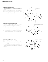
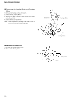
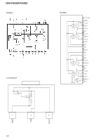
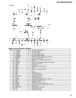
DEH-P900R,P9050 - Removing the Guide Arm Assy 1. Remove a connector, a spring A and B 2. Drive the Guide Arm Assy up aslant into rear side direction, then remove it from a Pin. Finally, drive the assembly approximately 45 degrees upward, then slide the assembly toward left side to remove it. Note : When assembling the guide arm assembly, route the cord inside the assembly. In this operation, care must be exercised so that cord may be caught by the gear. Guide Arm Assy Section A - Removing the LO Arm Assy 1. Remove two Pins to dismount the LO Arm Assy. LO Arm Assy Section B Pin - Removing the Control Unit and the Spindle Motor 1. Remove from the connector after mounting the short pin on the flexible PCB of the pickup unit. 2. Remove two Soldered joints, then remove two Screws A. 3. Remove two connectors and a Screw B. 4. Disengage the Control Unit from two Tabs, then dis- mount the unit by sliding it toward left. 5. Dismount the Spindle Motor. Short Pin Spindle Motor B Control Unit AA 65
-
 1
1 -
2
-
3
-
4
-
5
-
6
-
7
-
8
-
9
-
10
-
11
-
12
-
13
-
14
-
15
-
16
-
17
-
18
-
19
-
20
-
21
-
22
-
23
-
24
-
25
-
26
-
27
-
28
-
29
-
30
-
31
-
32
-
33
-
34
-
35
-
36
-
37
-
38
-
39
-
40
-
41
-
42
-
43
-
44
-
45
-
46
-
47
-
48
-
49
-
50
-
51
-
52
-
53
-
54
-
55
-
56
-
57
-
58
-
59
-
 60
60 -
 61
61 -
 62
62 -
 63
63 -
 64
64 -
 65
65 -
 66
66 -
 67
67 -
 68
68 -
 69
69 -
 70
70 -
71
-
72
-
73
-
74
-
75
-
76
-
77
-
78
-
79
-
80
-
81
-
82
-
83
-
84
-
85
-
86
-
87
-
88
-
89
 |
 |
