Pioneer DEH-P900R Service Manual - Page 70
Pioneer DEH-P900R Manual
 |
View all Pioneer DEH-P900R manuals
Add to My Manuals
Save this manual to your list of manuals |
Page 70 highlights
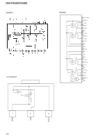
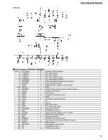
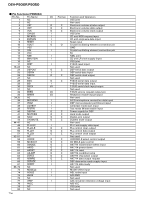
DEH-P900R,P9050 Pin No. 31 32 33 34 35 36 37 38 39 40 41 42 43 44 45 46 47 48 49 50-61 62 63 64 65 66 67 68 69 70 71 72 73 74 75 76 77 78 79 80 81 82 83 84 85 86 87 88 89,90 91 92 93 94 95 96 97 98 99 100 Pin Name BSO BSI BSCK FLPOPN DPDT KYDT FLPCLS FOPENSW NC FCLSSW DLED NC FLPILM ILMPW SWVDD OELPW DSENS ST SD NC VCC3 NC VSS4 VCK/ROMCLK VDT/ROMDATA VST/BSRQ2 NC BRXEN BRST BSRQ NC BSENS ASENS STOUT DRELAY LOCH LOCL NC NC FM/AM TMUTE DRST RDSLK RDT DRSENS DRSYS TESTIN NC LEVELR LEVELL NC SD_BW NC VSS5 SL VREF VCC4 TUNPDI I/O Function and Operation O P-BUS communication data output I P-BUS communication data input I/O P-BUS serial clock input/output O Flap motor open output O Display serial data output I Display enable data input O Flap motor close output I Flap open switch input Not used I Flap close switch input O Alarm LED output Not used O Inside of flap illumination output O Illumination power supply control output O Display chip select output O OEL module power supply control output I Grille detach sense input I FM stereo input I SD input Not used 5V Not used GND O E-VOL clock output / ROM correction clock output O/I E-VOL data output / ROM correction data input O/I E-VOL strobe pulse output / P-BUS communication input/output Not used I/O P-BUS communication input/output O P-BUS reset output I/O P-BUS communication request input/output Not used I Back up power sense input I ACC power sense input O Starter cut output O External relay output O Local "H" output O Local "L" output Not used O Open O FM/AM power select output O Tuner mute output O RDS decoder reset output I RDS lock signal input I RDS data input I Door open/close sense input O Door system select output I Test mode IN/test enable Not used I Level meter "R" AD input I Level meter "L" AD input Not used I SD input Not used GND I Signal level input A/D converter reference voltage 5V I PLL data input 70
-
 1
1 -
2
-
3
-
4
-
5
-
6
-
7
-
8
-
9
-
10
-
11
-
12
-
13
-
14
-
15
-
16
-
17
-
18
-
19
-
20
-
21
-
22
-
23
-
24
-
25
-
26
-
27
-
28
-
29
-
30
-
31
-
32
-
33
-
34
-
35
-
36
-
37
-
38
-
39
-
40
-
41
-
42
-
43
-
44
-
45
-
46
-
47
-
48
-
49
-
50
-
51
-
52
-
53
-
54
-
55
-
56
-
57
-
58
-
59
-
60
-
61
-
62
-
63
-
64
-
 65
65 -
 66
66 -
 67
67 -
 68
68 -
 69
69 -
 70
70 -
 71
71 -
 72
72 -
 73
73 -
 74
74 -
 75
75 -
76
-
77
-
78
-
79
-
80
-
81
-
82
-
83
-
84
-
85
-
86
-
87
-
88
-
89
 |
 |
