Pioneer DEH-P900R Service Manual - Page 69
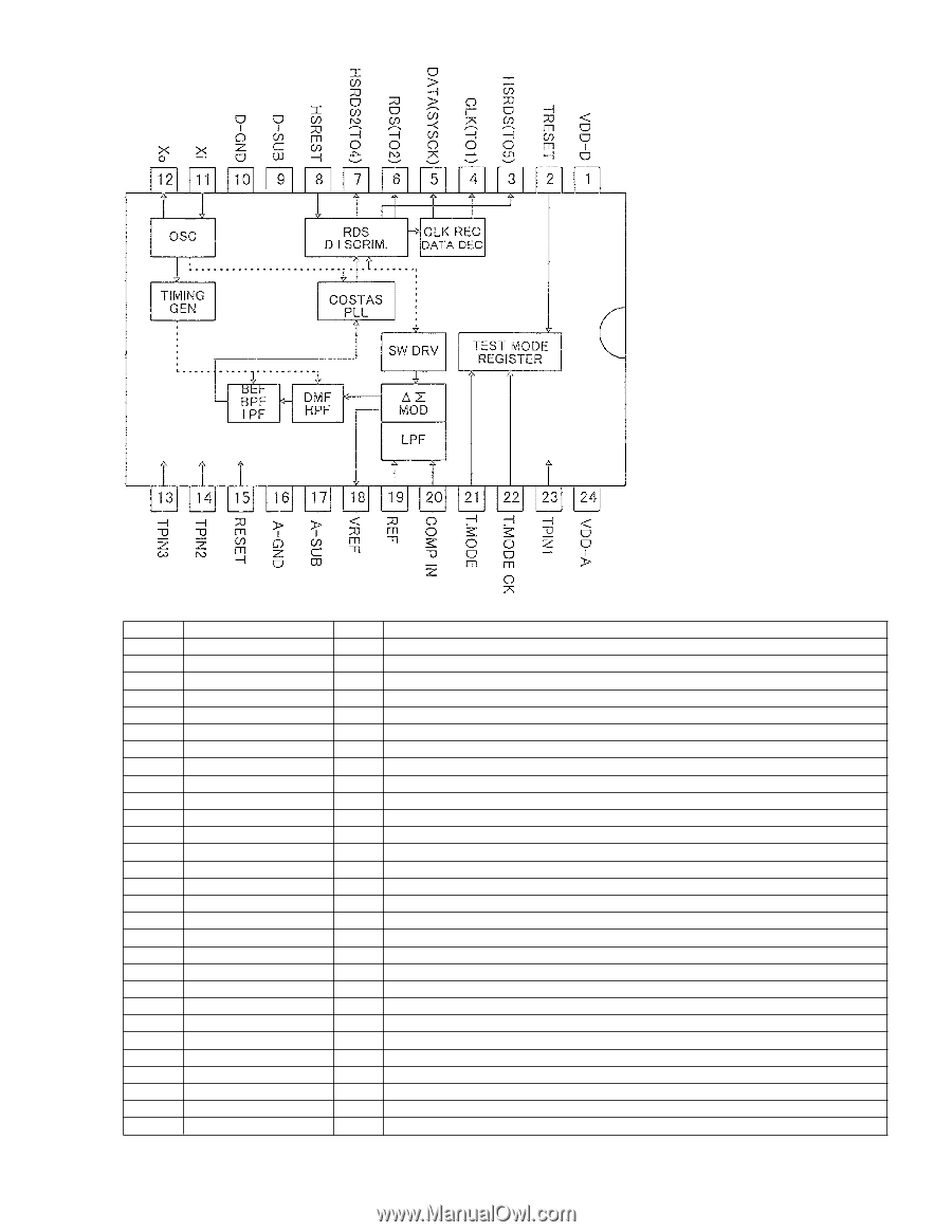
Pin Functions PD5483A, PD5484A
 |
View all Pioneer DEH-P900R manuals
Add to My Manuals
Save this manual to your list of manuals |
Page 69 highlights
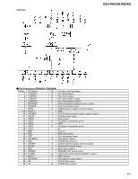
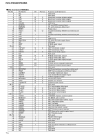
PM4009A DEH-P900R,P9050 - Pin Functions (PD5483A, PD5484A) Pin No. Pin Name I/O Function and Operation 1 TUNPDO O PLL data output 2 TUNPCK O PLL clock output 3 TUNPCE O PLL chip enable output 4 TUNPCE2 O PLL chip enable output 2 5 MOSENS I Motion/window damage sensor input 6 DLSENS I Door lock sense input 7 IPPW O IP-BUS power supply control output 8,9 VSS1,2 GND 10 ASENBO O IP-BUS slave power supply control output 11 TELIN I Cellular mute input 12 RESET I Reset input 13 OSC1 O Oscillator connection pin 1 14 VSS3 GND 15 OSC2 O Oscillator connection pin 2 16 VCC1 5V 17 NMI Pull up 18 rck I RDS clock input 19 ldet I PLL lock sense input 20 DALMON O DFS alarm output 21 RX2 I IP-BUS data input 2 22 SYSPW O System power supply control output 23 ISENS I Illumination sense input 24 PEE O Beep tone output 25 RDS57K I 57kHzBP-OUT sense input 26 FLPPW O Flap motor driver power ON/OFF output 27 MUTE O Mute output 28 MICSENS I Microphone sense input 29 RX I IP-BUS data input 30 TX O IP-BUS data output 69
-
 1
1 -
2
-
3
-
4
-
5
-
6
-
7
-
8
-
9
-
10
-
11
-
12
-
13
-
14
-
15
-
16
-
17
-
18
-
19
-
20
-
21
-
22
-
23
-
24
-
25
-
26
-
27
-
28
-
29
-
30
-
31
-
32
-
33
-
34
-
35
-
36
-
37
-
38
-
39
-
40
-
41
-
42
-
43
-
44
-
45
-
46
-
47
-
48
-
49
-
50
-
51
-
52
-
53
-
54
-
55
-
56
-
57
-
58
-
59
-
60
-
61
-
62
-
63
-
 64
64 -
 65
65 -
 66
66 -
 67
67 -
 68
68 -
 69
69 -
 70
70 -
 71
71 -
 72
72 -
 73
73 -
 74
74 -
75
-
76
-
77
-
78
-
79
-
80
-
81
-
82
-
83
-
84
-
85
-
86
-
87
-
88
-
89
 |
 |