Pioneer DJM-500 Owner's Manual - Page 7
Connection of Outputs, Microphones, Etc. - knobs
 |
View all Pioneer DJM-500 manuals
Add to My Manuals
Save this manual to your list of manuals |
Page 7 highlights
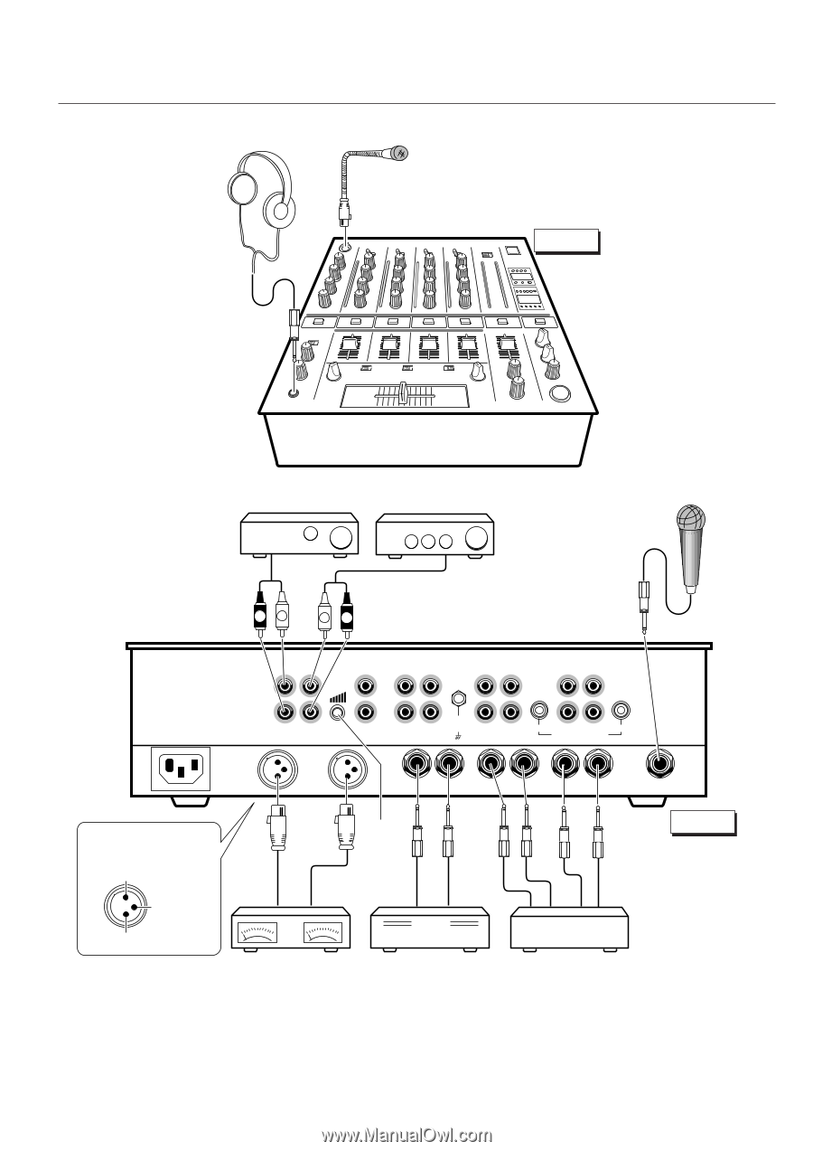
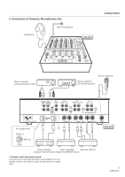
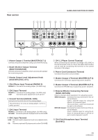
2. Connection of Outputs, Microphones, Etc. Headphone Main microphone DJM-500 CONNECTIONS Power amplifier (Supporting RCA input) Sub microphone Power amplifier (For booth monitor) R L L R MASTER BOOTH OUT 1 MONITOR L CH - 4 PHONO 3 CH - 3 PHONO 2 LINE L L CH - 2 PHONO 1 CD 2 / LINE CH - 1 LINE CD 1 L L R R R MASTER LEVEL ATT. R SIGNAL GND R CH - 2 CH - 1 PLAYER CONTROL ~AC IN R MASTER OUT 2 R LR LR L CH - 4 L MASTER OUT 3 SEND (MONO) RETURN (MONO) SUBMIC Pin assignment *1 DJM-500 COLD (-) 23 1 HOT (+) GND Power amplifier Power amplifier External effector (Supporting XLR input) (Supporting PHONE input) *1 Master level attenuator knob To protect the connected amplifiers and speakers from excessive inputs, this knob is used to decrease the output level. 7
-
 1
1 -
 2
2 -
 3
3 -
 4
4 -
 5
5 -
 6
6 -
 7
7 -
 8
8 -
 9
9 -
 10
10 -
 11
11 -
 12
12 -
13
-
14
-
15
-
16
-
17
-
18
-
19
-
20
 |
 |