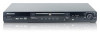
Pioneer DVD-V5000 Owner's Manual - Page 10
Connecting up - manual
 |
UPC - 012562689661
View all Pioneer DVD-V5000 manuals
Add to My Manuals
Save this manual to your list of manuals |
Page 10 highlights
02 Connecting up Chapter 2 Connecting up Rear panel connections 1 23 8 7 6 5 4 When connecting this player up to your TV, AV receiver or other components, make sure that all components are switched off and unplugged. 1 DIGITAL AUDIO OUT This is a digital audio output for connection to a PCM, Dolby Digital and/or DTS-compatible AV receiver that has a coaxial digital input. Connect using a commercially available coaxial digital cable. 2 COMPONENT VIDEO OUT This is a high quality video output for connection to a TV, monitor or AV receiver that has component video inputs. Connect using a commercially available threeway component video cable. Be careful to match the colors of the jacks and cables for correct connection. 3 AUDIO OUT L / R This pair of analog audio outputs connects to your TV, AV receiver or stereo system. Even if you are connecting up one of the digital outputs, we still recommend you connect these jacks. Use the supplied audio/video cable when connecting these jacks. Match the colors of the jacks and cables for correct stereo sound. 10 4 AC IN Connect the supplied power cable here, then plug into a power outlet. 5 VIDEO OUT This is a standard video output that you can connect to your TV or AV receiver using the supplied audio/video cable. 6 S (S-video output) This is an S-video output that you can use instead of the video output described in 5 above. 7 RS-232C This is a RS-232C terminal (D-sub 9-pin, male). 8 EXT TERMINAL This is a RS-232C and Extend terminal (D-sub 15pin, female). You may find it useful to have the manuals supplied with your other components handy when connecting this player.
-
 1
1 -
2
-
3
-
4
-
 5
5 -
 6
6 -
 7
7 -
 8
8 -
 9
9 -
 10
10 -
 11
11 -
 12
12 -
 13
13 -
 14
14 -
 15
15 -
16
-
17
-
18
-
19
-
20
-
21
-
22
-
23
-
24
-
25
-
26
-
27
-
28
-
29
-
30
-
31
-
32
-
33
-
34
-
35
-
36
-
37
-
38
-
39
-
40
-
41
-
42
-
43
-
44
-
45
-
46
-
47
-
48
-
49
-
50
-
51
-
52
-
53
-
54
-
55
-
56
-
57
-
58
-
59
-
60
-
61
-
62
-
63
-
64
-
65
-
66
-
67
-
68
-
69
-
70
-
71
-
72
-
73
-
74
-
75
-
76
-
77
-
78
-
79
-
80
 |
 |
