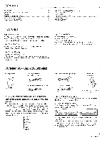
Pioneer F-93 Operating Instructions - Page 5
CONNECTION, Connecting, Power, Connection, applicable, model, ATTACH, ANTENNA, ADAPTOR, supplied,
 |
View all Pioneer F-93 manuals
Add to My Manuals
Save this manual to your list of manuals |
Page 5 highlights
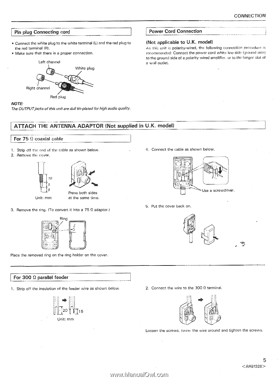
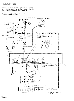
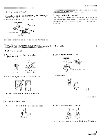
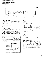
Pin plug Connecting cord • Connect the white plug to the white terminal IL) and the red plug to the red terminal (R). • Make sure that there is a proper connection. Left channel White plug Fv6..,...cl,._._ Right channel fal, Red plug NOTE: The OUTPUTjacks of this unit are dull tin-plated for high audio quality. CONNECTION Power Cord Connection (Not applicable to U.K. model) As this unit is polarity-wired, the following connection procedure is recommended: Connect the power cord white line side (ground side) to the ground side of a polarity-wired amplifier, or to the longer slot of a wall outlet. ATTACH THE ANTENNA ADAPTOR (Not supplied in U.K. model) For 75 S1 coaxial cable 1. Strip off the end of the cable as shown below. 2. Remove the cover. 4. Connect the cable as shown below. -y Unit: mm Press both sides at the same time. 3. Remove the ring. To convert it into a 75 0 adaptor.) Ring + 4- Use a screwdriver. 5. Put the cover back on. Place the removed ring on the ring holder on the cover. For 300 0 parallel feeder 1. Strip off the insulation of the feeder wire as shown below. 120 115 Unit: mm 2. Connect the wire to the 300 0 terminal. Loosen the screws, twine the wire around and tighten the screws. 5
-
 1
1 -
 2
2 -
 3
3 -
 4
4 -
 5
5 -
 6
6 -
 7
7 -
 8
8 -
 9
9 -
 10
10 -
 11
11 -
12
-
13
-
14
-
15
-
16
 |
 |