Pioneer GM-A5702 Owners Manual - Page 11
Connections when using, the speaker input wire, Connecting the power, terminal, Connecting the units
 |
View all Pioneer GM-A5702 manuals
Add to My Manuals
Save this manual to your list of manuals |
Page 11 highlights
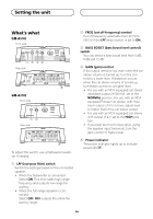
Connecting the units Connections when using the speaker input wire Connect the car stereo speaker output wires to the amplifier using the supplied speaker input wire. ! Do not connect both the RCA input and the speaker input at the same time. Connecting the power terminal The use of a special red battery and ground wire RD-223 (sold separately) is recommended. Connect the battery wire directly to the car battery positive terminal + and the ground wire to the car body. 1 Car Stereo 2 Speaker output 3 White/black: Left * 4 White: Left + 5 Gray/black: Right * 6 Gray: Right + 7 Speaker input connector To speaker input terminal of this unit. Note If speaker input wires from a headunit are connected to this amplifier, the amplifier will automatically turn on when the headunit is turned on. When the headunit is turned off, the amplifier turns off automatically. This function may not work with some headunits. In such cases, make sure that the Left channel is connected correctly. If the function still does not work, please use a system remote control wire (sold separately). If multiple amplifiers are to be connected together synchronously, connect the head unit and all amplifiers via the system remote control wire. WARNING If the battery wire is not securely fixed to the terminal using the terminal screws, there is a risk of overheating, malfunction and injury, including minor burns. 1 Route battery wire from engine compartment to the vehicle interior. ! When drilling a cable pass-hole into the vehicle body and routing a battery wire thorough it, take care not to short-circuit the wire damaging it by the cut edges or burrs of the hole. After completing all other amplifier connections, finally connect the battery wire terminal of the amplifier to the positive + battery terminal. 1 Positive + terminal 2 Engine compartment 3 Vehicle interior 4 Fuse (30 A) × 2 5 Insert the O-ring rubber grommet into the vehicle body. 6 Drill a 14 mm (1/2 in.) hole into the vehicle body. En
-
 1
1 -
2
-
3
-
4
-
5
-
 6
6 -
 7
7 -
 8
8 -
 9
9 -
 10
10 -
 11
11 -
 12
12 -
 13
13 -
 14
14 -
 15
15 -
 16
16 -
17
-
18
-
19
-
20
-
21
-
22
-
23
-
24
-
25
-
26
-
27
-
28
-
29
-
30
-
31
-
32
 |
 |
