Pioneer GM-A5702 Owners Manual - Page 8
Connection diagram, Connecting the units
 |
View all Pioneer GM-A5702 manuals
Add to My Manuals
Save this manual to your list of manuals |
Page 8 highlights
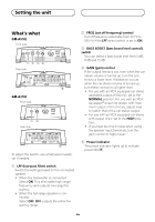
Connecting the units Connection diagram Connect male terminal of this wire to the system remote control terminal of the car stereo. The female terminal can be connected to the auto-antenna relay control terminal. If the car stereo lacks a system remote control terminal, connect the male terminal to the power terminal via the ignition switch. 9 Speaker output terminals Please see the following section for speaker connection instructions. Refer to Connecting the speakers. a Fuse 30 A × 2 (GM-A5702) / 25 A × 1 (GMA3702) b Fuse (30 A) × 2 c Grommet d Rear side e Front side 1 Special red battery wire RD-223 (sold separately) After completing all other amplifier connections, finally connect the battery wire terminal of the amplifier to the positive + battery terminal. 2 Ground wire (Black) RD-223 (sold separately) Connect to metal body or chassis. 3 Car stereo with RCA output jacks (sold separately) 4 External output 5 Connecting wire with RCA pin plugs (sold se- parately) 6 Speaker input terminal (use a connector in- cluded) Please see the following section for speaker connection instructions. Refer to Connections when using the speaker input wire. 7 RCA input jack 8 System remote control wire (sold separately) En
-
 1
1 -
2
-
 3
3 -
 4
4 -
 5
5 -
 6
6 -
 7
7 -
 8
8 -
 9
9 -
 10
10 -
 11
11 -
 12
12 -
 13
13 -
14
-
15
-
16
-
17
-
18
-
19
-
20
-
21
-
22
-
23
-
24
-
25
-
26
-
27
-
28
-
29
-
30
-
31
-
32
 |
 |
