Pioneer PDA-5004 Operating Instructions - Page 7
Part Names and Functions - pda 5003 and
 |
UPC - 012562691091
View all Pioneer PDA-5004 manuals
Add to My Manuals
Save this manual to your list of manuals |
Page 7 highlights
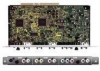
English Part Names and Functions Connection panel POWER OFF ON AC IN Illustration depicts PDP-504CMX/ PDP-50MXE1/PDP-50MXE1-S model. When installing PDA-5003 S-VIDEO INPUT3 VIDEO INPUT4 INPUT 3/4 AUDIO 0 - ANALOG RGB INPUT5 AUDIO IN OUT R L G(ON SYNC) B R HD (H/V SYNC) VD R L ~ !@ # When installing PDA-5004 S-VIDEO INPUT3 AUDIO VIDEO INPUT4 $ COMPONENT AUDIO VIDEO INPUT5 R L IN OUT R L Y Pb/Cb Pr/Cr % AUDIO R L ^ & *( ) _ + SPEAKER 8+Ω ~16Ω- L = Part Names and Functions R SPEAKER 8+Ω ~16Ω- 1 IN OUT COMBINATION 2 RS-232C 3 ANALOG RGB IN D-Sub ANALOG RGB OUT D-Sub INPUT1 AUDIO DIGITAL RGB DVI-D INPUT2 OUTPUT AUDIO AUDIO 4 5 6 7 89 Plasma Display Section The plasma display is provided with 2 video input connectors, 1 video output connector, audio input/output jacks and speaker terminals. When this video card is installed on a plasma display, an additional three sets of video input connectors are provided (total five), together with one additional video output connector (total two). See the pages noted in parentheses ( ) or the plasma display's Operating Instructions for details regarding connections to the various jacks and connectors. 1 SPEAKER (R) terminal For connection of an external right speaker. Connect a speaker whose impedance is 8 -16 Ω. 2 COMBINATION IN/OUT Never connect any component to these connectors without first consulting your Pioneer installation technician. These connectors are used for plasma display setup adjustments. 3 RS-232C Never connect any component to this connector without first consulting your Pioneer installation technician. This connector is used for plasma display setup adjustments. 4 En 4 ANALOG RGB IN (INPUT1) (mini D-sub 15 pin) For connecting components equipped with RGB outputs jacks, such as a personal computer or external RGB decoder; or components equipped with component output jacks, such as a DVD recorder. Make sure that the connection made corresponds to the format of the signal output from the connected component (pages 7 to 10). 5 ANALOG RGB OUT (INPUT1) (mini D-sub 15 pin) Use the ANALOG RGB OUT (INPUT1) connector to output the video signal to an external monitor or other component. Note: The video signal will not be output from the ANALOG RGB OUT (INPUT1) connector when the main power of this display is off or in standby mode (page 10). 6 AUDIO (INPUT1) (Stereo mini jack) Use to obtain sound when INPUT1 is selected. Connect this jack to the audio output connector of the device connected to the plasma display's INPUT1 (page 15). 7 DIGITAL RGB (INPUT2) (DVI-D jack) Use to connect a computer. Note: This unit does not support the display of copyguard-protected video signals (page 13).
-
 1
1 -
 2
2 -
 3
3 -
 4
4 -
 5
5 -
 6
6 -
 7
7 -
 8
8 -
 9
9 -
 10
10 -
 11
11 -
 12
12 -
13
-
14
-
15
-
16
-
17
-
18
-
19
-
20
-
21
-
22
-
23
-
24
-
25
-
26
-
27
-
28
-
29
-
30
-
31
-
32
-
33
-
34
-
35
-
36
-
37
-
38
-
39
-
40
-
41
-
42
-
43
-
44
-
45
-
46
-
47
-
48
-
49
-
50
-
51
-
52
-
53
-
54
-
55
-
56
-
57
-
58
-
59
-
60
-
61
-
62
-
63
-
64
-
65
-
66
-
67
-
68
-
69
-
70
-
71
-
72
-
73
-
74
-
75
-
76
-
77
-
78
-
79
-
80
-
81
-
82
-
83
-
84
-
85
-
86
-
87
-
88
-
89
-
90
-
91
-
92
-
93
-
94
-
95
-
96
-
97
-
98
-
99
 |
 |
