Pioneer PDP-503CMX Technical Manual - Page 12
Controls and Connectors - plasma
 |
View all Pioneer PDP-503CMX manuals
Add to My Manuals
Save this manual to your list of manuals |
Page 12 highlights
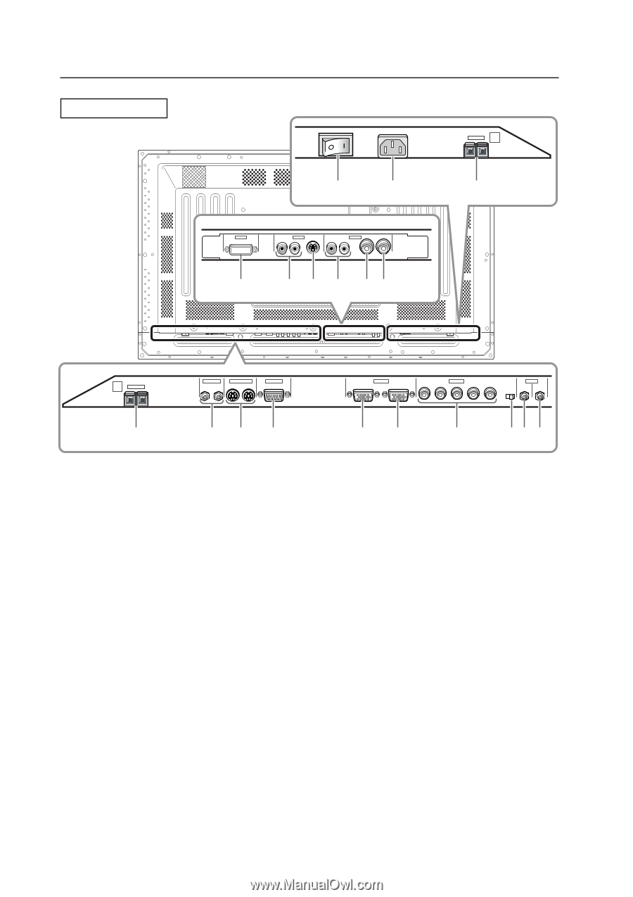
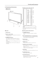
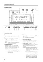
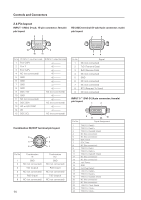
Controls and Connectors Connection Panel AC INLET OFF ON - = INPUT5 DIGITAL RGB AUDIO R INPUT3 S-VIDEO L AUDIO R INPUT4 VIDEO L OUTPUT ! @ # $ %^ 8Ω ~16Ω SPEAKER + - L ~ R 8Ω ~16Ω S+PEAKE-R 1 CONTROL IN OUT COMBINATION IN OUT RS-232C 23 4 INPUT1 (ON SYNC) ANALOG RGB OUTPUT (ANALOG RGB) G B INPUT2 (H/V SYNC) R HD VD 7Ω5Ô2k.Ω2 AUDIO INPUT OUTPUT (INPUT1/2) 56 7 89 0 Plasma Display Section 1 SPEAKER (R) terminal For connection of an external right speaker. Connect a speaker whose impedance is 8 -16 Ω. 2 CONTROL IN/OUT (monaural mini jacks) For connection of PIONEER components that bear the Î mark. Making CONTROL connection enables control of the main unit as a component in a system. (NOTE) The main unit cannot be operated by the wired remote control RV-V107. 3 COMBINATION IN/OUT Used when a number of sets are controlled collectively. (See "5.6 Combination Connection") Please use a mini DIN 6 pin cable (straight, fully connected) available on the market as the connecting cable. (NOTE) It has no ABL linking function. And it is not compatible with the RM-V4000V or other multi-projection. It is not output when the main power is off. 12 4 RS-232C This terminal is used for adjustments by a PC (EIA232-F standard). (See "5.5 RS-232C Adjustment Mode") 5 INPUT1 (mini D-sub 15 pin) For connection of components that have RGB or component# output jacks such as a personal computer, DVD player, or external RGB decoder. 6 OUTPUT (INPUT1) (mini D-sub 15 pin) Use the OUTPUT (INPUT1) connector to output the video signal to an external monitor or other component. (NOTE) • The video signal will not be output from the OUTPUT (INPUT1) connector when the main power of this display is off or in standby mode. • When connecting the main units in a series, please set the number that can be connected as a total of 5 including the set that the signal is initially input to. But a condition for performing separate sink or composite sink input and output is that the sink level of the source used is at least TTL level at 2.2kΩ terminal time.
-
 1
1 -
2
-
3
-
4
-
5
-
6
-
 7
7 -
 8
8 -
 9
9 -
 10
10 -
 11
11 -
 12
12 -
 13
13 -
 14
14 -
 15
15 -
 16
16 -
 17
17 -
18
-
19
-
20
-
21
-
22
-
23
-
24
-
25
 |
 |