Pioneer PDP-503CMX Technical Manual - Page 23
Mounting surface warping - plasma display
 |
View all Pioneer PDP-503CMX manuals
Add to My Manuals
Save this manual to your list of manuals |
Page 23 highlights
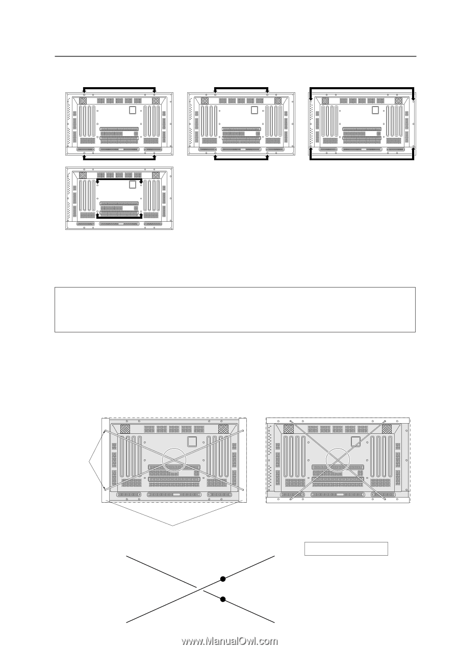
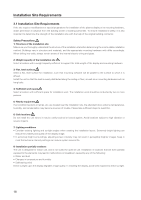
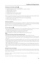
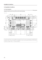
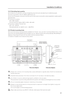
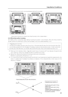
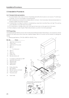
D. Secured at four points (with mounting hardware attached horizontally) Installation Conditions (Take proper precautions to prevent pinching the power cord or signal cables.) 3.2.4 Mounting surface warping The display section incorporates glass. Before mounting the product, using hardware other than that provided by Pioneer, perform the following to confirm that the display is free from warps exceeding 1 mm*. * Regarding the 1mm limit The frame of the display may have a warp of up to 3mm. If the total warp (the warp of the frame plus the warp of the mount surface) exceeds 4mm then the glass in the display may be put under excessive stress. In order to ensure that the total warp is less than 4mm, you should make sure that the warp of the mount surface is less than 1mm. 1 Referring to the illustration below, diagonally extend string of maximum φ 0.1-mm diameter through the bolt mount openings. Strings thus arranged should be completely free of slack. 2 Measure the clearance (L) between the strings at their point of intersection. Distortion is expressed by: [Distortion] = L × 2. 3 If L is found to be 0, pass the strings through the other bolt mount openings and repeat the measurements. Any value of L greater than 0 indicates the presence of distortion. If the measured value in both cases is 0, the distortion is negligible. A A Mount bolt holes Plasma Display Mount Surface (Mount Brackets) A String F E String C D Magnified view of section A Point E is the center point of string segment A-B. Point F is the center point of string segment C-D. Clearance between points E and F = L. (Points E and F are shown displaced for illustrative purposes.) B 23
-
 1
1 -
2
-
3
-
4
-
5
-
6
-
7
-
8
-
9
-
10
-
11
-
12
-
13
-
14
-
15
-
16
-
17
-
 18
18 -
 19
19 -
 20
20 -
 21
21 -
 22
22 -
 23
23 -
 24
24 -
 25
25
 |
 |