Pioneer PRS-D2000SPL Owner's Manual - Page 17
Example of installation on the floor, mat or on the chassis, Replacing the terminal cover, Changing
 |
UPC - 012562858937
View all Pioneer PRS-D2000SPL manuals
Add to My Manuals
Save this manual to your list of manuals |
Page 17 highlights
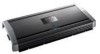
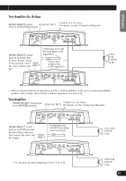
ENGLISH ESPAÑOL DEUTSCH FRANÇAIS ITALIANO NEDERLANDS Example of installation on the floor mat or on the chassis 1. Place the amplifier where it is to be installed. Insert the supplied tapping screws (4 mm × 18 mm) into the screw holes. Push on the screws with a screwdriver so they make marks where the installation holes are to be located. 2. Drill 2.5 mm (1/8 in.) diameter holes at the point marked, and install the amplifier, either on the carpet or directly to the chassis. Replacing the terminal cover 1. Align the unit and terminal cover, and insert the screw. 2. Tighten the screw with a 4 mm hexagonal wrench. Screw Terminal Cover Tapping screw (4 mm × 18 mm) Floor mat or chassis Drill a 2.5 mm (1/8 in.) diameter hole Changing the Direction of the Badge 1. To remove the badge, loose screws by using a 2 mm hexagonal wrench. 2. Change the direction of badge, and then tighten the screws with a hexagonal wrench. Screw Badge 16
-
 1
1 -
2
-
3
-
4
-
5
-
6
-
7
-
8
-
9
-
10
-
11
-
 12
12 -
 13
13 -
 14
14 -
 15
15 -
 16
16 -
 17
17 -
 18
18 -
 19
19 -
 20
20 -
 21
21 -
 22
22 -
23
-
24
-
25
-
26
-
27
-
28
-
29
-
30
-
31
-
32
-
33
-
34
-
35
-
36
-
37
-
38
-
39
-
40
-
41
-
42
-
43
-
44
-
45
-
46
-
47
-
48
-
49
-
50
-
51
-
52
-
53
-
54
-
55
-
56
 |
 |
