Pioneer PRS-D2000SPL Owner's Manual - Page 9
Solderless Terminal Connections, Connecting the Speaker Output, Terminals
 |
UPC - 012562858937
View all Pioneer PRS-D2000SPL manuals
Add to My Manuals
Save this manual to your list of manuals |
Page 9 highlights
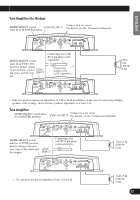
ENGLISH ESPAÑOL DEUTSCH FRANÇAIS ITALIANO NEDERLANDS Solderless Terminal Connections • Since the wire will become loose over time, it must be periodically inspected and tightened as necessary. • Do not solder or bind the ends of the twisted wires. • Fasten while making sure to not to clamp the insulating sheath of the wire. • Use the supplied hexagonal wrench to tighten and loosen the terminal screw of the amplifier. Securely fasten the wire with the terminal screw. However, since excessively tightening the terminal screw of the System remote control has the risk of damaging the wire, be careful not to tighten excessively by observing the status of the wire when tightening. Connecting the Speaker Output Terminals Speaker Wire Size less than 4.3 m less than 6.4 m less than 10.7 m Wire Length less than 14 ft. less than 21 ft. less than 35 ft. Wire Size 8 AWG 6 AWG 4 AWG 1. Expose the end of the speaker wires using nippers or a cutter by about 18 mm to 20 mm (3/4 in.). 18 mm to 20 mm (3/4 in.) 2. Connect the speaker wires to the speaker output terminals. • Fix the speaker wires securely with the terminal screws. Terminal screw Speaker output terminal Speaker wire 3. Put the wire ties in the slits and wrap the wire ties around the wires. • Wrap the wire tie around the wire insulation, not the stripped wire. • Cut off any excess portions of the wire ties. Wire tie 8
-
 1
1 -
2
-
3
-
 4
4 -
 5
5 -
 6
6 -
 7
7 -
 8
8 -
 9
9 -
 10
10 -
 11
11 -
 12
12 -
 13
13 -
 14
14 -
15
-
16
-
17
-
18
-
19
-
20
-
21
-
22
-
23
-
24
-
25
-
26
-
27
-
28
-
29
-
30
-
31
-
32
-
33
-
34
-
35
-
36
-
37
-
38
-
39
-
40
-
41
-
42
-
43
-
44
-
45
-
46
-
47
-
48
-
49
-
50
-
51
-
52
-
53
-
54
-
55
-
56
 |
 |
