Pioneer SDV-P7 Other Manual - Page 2
When Connecting the Head Unit, When Connecting the Display with RCA Input Jacks, When Using - installation manual
 |
View all Pioneer SDV-P7 manuals
Add to My Manuals
Save this manual to your list of manuals |
Page 2 highlights
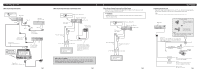
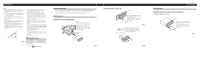
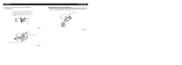
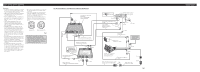
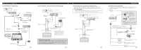
Connecting the Units When Connecting the Head Unit IP-BUS STAND ALONE This product Not used. Blue 15 cm 40 cm Blue Head Unit (sold separately) Blue IP-BUS cable (sold separately) AV-BUS cable (sold separately) IP-BUS cable (supplied with the TV tuner) FM MODULATOR IP-BUS MAIN UNIT IP-BUS AV MASTER Black Hide-away TV Tuner (e.g. GEX-P7000TV) (sold separately) Red AV system display (e.g. AVX-7300) (sold separately) 20 pin cable (supplied with the display) Green Red Fig. 3 When Connecting the Display with RCA Input Jacks IP-BUS White (audio output (Left)) STAND ALONE Red (audio output (Right)) This product Yellow (front video output) Remote sensor (sold separately) RCA cable (supplied) RCA cable (sold separately) To video input To audio inputs Display with RCA input jacks This product features a built-in remote sensor. If it is installed in a location where reception of the remote control signal is not possible, use a separately sold remote sensor. Connecting a rear display Instead of video output for viewing on a front display, you can connect for video output enabling viewing on a rear display (for passengers in the rear of the car). If you decide to use a rear display, be sure to follow the warnings on the next page. Fig. 4 When Using a Display Connected Rear Video Output This product's rear video output is for connection of a display to enable passengers in the rear seats to watch the DVD or Video CD. WARNING • NEVER install the display in a location that enables the Driver to watch the DVD or Video CD while Driving. IP-BUS White (audio output (Left)) STAND ALONE Red (audio output (Right)) This product Yellow (rear video output) RCA cable (supplied) RCA cable (sold separately) To video input To audio inputs Display with RCA input jacks Fig. 5 Connecting the Power Cord This product comes with two kinds of power cord. Use the short cord when installing this product in the dashboard, and the long cord when installing it on the floor. Note: • Use commercially available installation parts to install this product on the floor. This Product Connection method 1. Clamp the parking brake switch power supply side lead. 2. Clamp firmly with needle-nosed pliers. Note: • The position of the parking brake switch depends on the vehicle model. For details, consult the vehicle Owner's Manual or dealer. Light green Used to detect the ON/OFF status of the parking brake. This lead must be connected to the power supply side of the parking brake switch. Power supply side Ground side Parking brake switch Fuse resistor Fuse holder Red To electric terminal controlled by ignition switch (12 V DC) ON/OFF. Yellow To terminal always supplied with power regardless of ignition switch position. Black (ground) To vehicle (metal) body. Fig. 6
-
 1
1 -
 2
2 -
 3
3 -
 4
4 -
 5
5 -
 6
6 -
 7
7 -
 8
8
 |
 |
