Pioneer SDV-P7 Other Manual - Page 3
DIN Rear-mount, MODE Switch Setting, DIN Front/Rear-mount, DIN Front-mount - wiring
 |
View all Pioneer SDV-P7 manuals
Add to My Manuals
Save this manual to your list of manuals |
Page 3 highlights
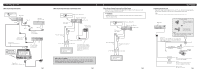
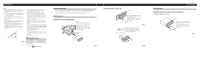
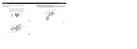
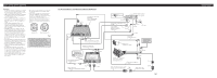
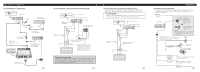
Installation Note: • Before finally installing the unit, connect the wiring temporarily, making sure it is all connected up properly, and the unit and the system work properly. • Use only the parts included with the unit to ensure proper installation. The use of unauthorized parts can cause malfunctions. • Consult with your nearest dealer if installation requires the drilling of holes or other modifications of the vehicle. • Install the unit where it does not get in the driver's way and cannot injure the passenger if there is a sudden stop, like an emergency stop. • The semiconductor laser will be damaged if it overheats, so don't install the unit anywhere hot - for instance, near a heater outlet. • If installation angle exceeds 30° from horizontal, the unit might not give its optimum performance. (Fig. 7) • When mounting this unit, make sure none of the leads are trapped between this unit and the surrounding metalwork or fittings. • Do not mount this unit near the heater outlet, where it would be affected by heat, or near the doors, where rainwater might splash onto it. • Before drilling any mounting holes always check behind where you want to drill the holes. Do not drill into the gas line, brake line, electrical wiring or other important parts. • If this unit is installed in the passenger compartment, anchor it securely so it does not break free while the car is moving, and cause injury or an accident. • If this unit is installed under a front seat, make sure it does not obstruct seat movement. Route all leads and cords carefully around the sliding mechanism so they do not get caught or pinched in the mechanism and cause a short circuit. • Do not mount this unit on the spare tire board or any other unstable place. • Do not mount this unit anywhere that gets the sun and so becomes hot, like on the dashboard or the rear shelf. • Mount this unit on a flat surface. Fig. 7 MODE Switch Setting Before installing, use a pen tip or other thin, pointed instrument to set the MODE Switch to the appropriate position for the component you are using it with. IP-BUS STAND ALONE DIN Front/Rear-mount This unit can be properly installed either from "Front" (conventional DIN Front-mount) or "Rear" (DIN Rear-mount installation, utilizing threaded screw holes at the sides of unit chassis). For details, refer to the following illustrated installation methods. DIN Front-mount Installation with the rubber bush (Fig. 8) Dashboard 182 Holder After inserting the holder into the dashboard, then select the appropriate tabs according to the thickness of the dashboard material and bend them. (Install as firmly as possible using the top and bottom tabs. To secure, bend the tabs 90 degrees.) 53 Rubber bush Screw Fig. 8 Removing the Unit (Fig. 9) (Fig. 10) F5rame I6nsert the release pin into the hole in the bottom of the frame and pull out to remove the frame. (When reattaching the frame, point the side with a groove downwards and attach it.) Insert the supplied extraction keys into the unit, as shown in the figure, until they click into place. Keeping the keys pressed against the sides of the unit, pull the unit out. Fig. 9 Fig. 10 DIN Rear-mount Installation using the screw holes on the side of the unit 1. Remove the frame. (Fig. 11) Frame Insert the release pin into the hole in the bottom of the frame and pull out to remove the frame. (When reattaching the frame, point the side with a groove downwards and attach it.) Fig. 11
-
 1
1 -
 2
2 -
 3
3 -
 4
4 -
 5
5 -
 6
6 -
 7
7 -
 8
8
 |
 |
