Pioneer VSX-07TX Service Manual - Page 64
Pioneer VSX-07TX Manual
 |
View all Pioneer VSX-07TX manuals
Add to My Manuals
Save this manual to your list of manuals |
Page 64 highlights
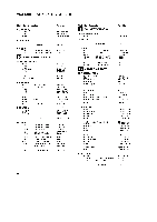
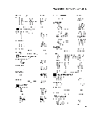
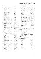
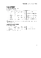
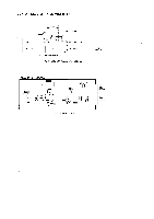
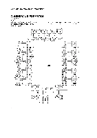
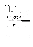
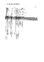
VSX-D906S, VSX-07TX, VSX-09TX 6. ADJUSTMENT 6.1 TUNER ADJUSTMENT • ADJUSTMENT OF FM TUNER SECTION • Set the FM/AM selector to FM BAND. • Connect the wiring as shown in Fig. 6-1 . Step No. Adjustment Title FM SC ( lkHz. -±75kHz dev.) Frequency (MHz) Level (dBµV) 1 Center Adjustment 98 Non 80 or more modulation Front End 2 Sensitivity adjustment 98 Low input (0 to 30) Stereo 3 Distortion 98 80 TUNED IND. 4 Lighting Level 98 15 (±2dB ) Reception Frequency Display 98MHz 98MHz Adjustment Location Specifications L6207 L6102 T6101 T6101 Adjust so that the DC voltage between IC6201-Pin 4 and Pin 28 (or + leads of C6224 and O6261) becomes 0V±50mV. Adjust so that the DC voltage between IC6201-Pin 12 and GND (or - leads of C6238 and GND) becomes at maximum level. Minimize the distortion with 1/8 rotation of the core. 98MHz VR6201 Adjust so that the indicator of TUNED IND. starts to light up. Votes: • Before adjusting, make sure there is no gap between L6101 and 1,6102 . If there is a gap between them, bring them into contact with each other first, and then make adjustments. • Make indicator adjustments in order ofAM FM. • ADJUSTMENT OF AM TUNER SECTION • Set the FM/AM selector to AM BAND. • Connect the wiring as shown in Fig. 6-1. Step No. Adjustment Title AM SG (400Hz, 30% Mod.) Frequency (kHz) Level (dBµV/m) Reception Frequency Display I TUNED IND. Lighting Level 999. ' 47(±-2dB) 999kHz.' *1: For the area using 101Hz step, frequencies should be 1000kHz Adjustment Location Specifications VR6202 Adjust so that the indicator of TUNED IND. starts to light up. 93
-
 1
1 -
2
-
3
-
4
-
5
-
6
-
7
-
8
-
9
-
10
-
11
-
12
-
13
-
14
-
15
-
16
-
17
-
18
-
19
-
20
-
21
-
22
-
23
-
24
-
25
-
26
-
27
-
28
-
29
-
30
-
31
-
32
-
33
-
34
-
35
-
36
-
37
-
38
-
39
-
40
-
41
-
42
-
43
-
44
-
45
-
46
-
47
-
48
-
49
-
50
-
51
-
52
-
53
-
54
-
55
-
56
-
57
-
58
-
 59
59 -
 60
60 -
 61
61 -
 62
62 -
 63
63 -
 64
64 -
 65
65 -
 66
66 -
 67
67 -
 68
68 -
 69
69 -
70
-
71
-
72
-
73
-
74
-
75
-
76
-
77
-
78
-
79
-
80
-
81
-
82
-
83
-
84
 |
 |
