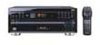
Pioneer VSX-07TX Service Manual - Page 75
Pioneer VSX-07TX Manual
 |
View all Pioneer VSX-07TX manuals
Add to My Manuals
Save this manual to your list of manuals |
Page 75 highlights
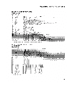
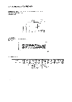
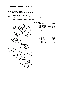
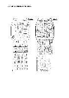
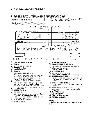
VSX-D906S, VSX-07TX, VSX-09TX 7.3 REMOTE CONTROL UNIT [CU-VSX117 (AXD7127) : KU AND KC TYPES] [CU-VSX122 (AXD7122) : SD AND KU/CA TYPES] 7.3.1 EXPLODED VIEWS AND PARTS LIST NOTES: • Parts marked by "NSP" are generally unavailable because they are not in our Master Spare Pans List. • The 1, markfound on some component parts indicates the importance of the safetyfactor of the part. Therefore, when replacing, be sum to use parts of identical designation. • Screws adjacent to V mark on product are usedfor disassembly. 16 15 14 2 d et, ft,)d dd .dam d 13 17 • Parts List Mark No. Description Parts No. 1 Filter AZA7I 52 2 Name Plate (KU AND KC TYPES) AZA7251 2 Name Plate (SD AND KU/CA TYPES) AZA7249 3 Rubber Sheet (A) AZA7236 4 Rubber Sheet (B) AZA7248 5 Spring (+) 6 Spring (-) 7 Spring 8 Screw 9 Remo-con Case (A) AZB7049 AZB7050 AZB7051 AZB7052 AZN7672 10 Remo-con Case (B) 11 Battery Cover 12 Main Key (FF) 13 Main Key (STOP) 14 Main Key (REV) AZN7326 AZN7327 AZN7666 AZN7329 AZN7665 NSP 15 Main Key (PAUSE) 16 Main Key (PLAY) 17 PCB AZN7331 AZN7664 AZW7243 10 11 1 O4
-
 1
1 -
2
-
3
-
4
-
5
-
6
-
7
-
8
-
9
-
10
-
11
-
12
-
13
-
14
-
15
-
16
-
17
-
18
-
19
-
20
-
21
-
22
-
23
-
24
-
25
-
26
-
27
-
28
-
29
-
30
-
31
-
32
-
33
-
34
-
35
-
36
-
37
-
38
-
39
-
40
-
41
-
42
-
43
-
44
-
45
-
46
-
47
-
48
-
49
-
50
-
51
-
52
-
53
-
54
-
55
-
56
-
57
-
58
-
59
-
60
-
61
-
62
-
63
-
64
-
65
-
66
-
67
-
68
-
69
-
 70
70 -
 71
71 -
 72
72 -
 73
73 -
 74
74 -
 75
75 -
 76
76 -
 77
77 -
 78
78 -
 79
79 -
 80
80 -
81
-
82
-
83
-
84
 |
 |
