Pioneer VSX-07TX Service Manual - Page 66
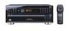
Pioneer VSX-07TX Manual
 |
View all Pioneer VSX-07TX manuals
Add to My Manuals
Save this manual to your list of manuals |
Page 66 highlights
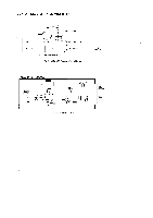
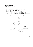
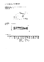
VSX-D906S, VSX-07TX, VSX-09TX 6.2 IDLE CURRENT ADJUSTMENT • CAUTION : Heatsinks' DC level is equal to +B or -B. Don't touch them or you will be electricary shocked. 1. Decrease the level of the Adjustment Variable resistor (VR) for the channel to be adjusted.(O)Turn counterclockwise.) 2. Set the power switch to ON. 3. While looking at voltage of the adjustment point shown below, gradually turn the Adjustment VR toward the right. Stop at 20mV. 4. Ages for ten minutes. 5. Readjust the voltage to 10 ± ImV after ten minutes. Adjustment is completed. ADJUSTMENT ch FLch FRch Cch SRch SLch ADJUSTMENT VR VR1052 VR I053 VR 1051 VR1055 VR1054 C) Heat Sink ADJUSTMENT POINT Voltage between IDLE CHK of Q42 and Q52, the terminal with a silk mark. Voltage between IDLE CHK of Q43 and Q53. the terminal with a silk mark. Voltage between IDLE CHK of Q41 and Q51, the terminal with a silk mark. Voltage between IDLE CHK of Q45 and Q55, the terminal with a silk mark. Voltage between IDLE CHK of Q44 and Q54, the terminal with a silk mark. Front Side C) Heat Sink O44 IDLE CHK. 0 DD VR1055 IDLE CHK. Q45 O54 VR1054 DD IDLE CHK. Q55 DD VR1051 IDLE CHK. O41 IDLE CHK. O51 DD VR1053 IDLE CHK. O43 IDLE CHK. O53 IDLE CHK. VR1052 Q42 0 IDLE CHK. O52 IDLE CHK. Rear Side c7FiR DRIVE ASSY • Example FLch Adjustment ADJUST DC Voltmeter 85
-
 1
1 -
2
-
3
-
4
-
5
-
6
-
7
-
8
-
9
-
10
-
11
-
12
-
13
-
14
-
15
-
16
-
17
-
18
-
19
-
20
-
21
-
22
-
23
-
24
-
25
-
26
-
27
-
28
-
29
-
30
-
31
-
32
-
33
-
34
-
35
-
36
-
37
-
38
-
39
-
40
-
41
-
42
-
43
-
44
-
45
-
46
-
47
-
48
-
49
-
50
-
51
-
52
-
53
-
54
-
55
-
56
-
57
-
58
-
59
-
60
-
 61
61 -
 62
62 -
 63
63 -
 64
64 -
 65
65 -
 66
66 -
 67
67 -
 68
68 -
 69
69 -
 70
70 -
 71
71 -
72
-
73
-
74
-
75
-
76
-
77
-
78
-
79
-
80
-
81
-
82
-
83
-
84
 |
 |
