| Section |
Page |
| Contents |
4 |
| Flow of settings on the receiver |
7 |
| 1 Before you start |
7 |
| j |
7 |
| 2 Determining the speakers’ application (page 15) |
7 |
| j |
7 |
| 3 Connecting the speakers |
7 |
| j |
7 |
| 4 Connecting the components |
7 |
| j |
7 |
| 5 Power On |
7 |
| j |
7 |
| 6 Changing the OSD display language (OSD Language) (page 37) |
7 |
| j |
7 |
| 7 MCACC speaker settings |
7 |
| j |
7 |
| 8 The Input Setup menu (page 40) |
7 |
| j |
7 |
| 9 Basic playback (page 42) |
7 |
| j |
7 |
| 10 Adjusting the sound and picture quality as desired |
7 |
| j |
7 |
| 11 Other optional adjustments and settings |
7 |
| j |
7 |
| 12 Making maximum use of the remote control |
7 |
| Before you start |
8 |
| Checking what’s in the box |
8 |
| Installing the receiver |
8 |
| Loading the batteries |
8 |
| CAUTION |
8 |
| Controls and displays |
9 |
| Front panel |
9 |
| 1 INPUT SELECTOR dial |
9 |
| 2 u STANDBY/ON |
9 |
| 3 SPEAKERS |
9 |
| 4 Remote sensor |
9 |
| 5 MULTI-ZONE controls |
9 |
| 6 Character display |
9 |
| 7 Indicators |
9 |
| 8 Tuner controls |
9 |
| 9 MASTER VOLUME dial |
10 |
| 10 PHONES jack |
10 |
| 11 Listening mode buttons |
10 |
| 12 iPod iPhone DIRECT CONTROL |
10 |
| 13 MCACC SETUP MIC jack |
10 |
| 14 iPod/iPhone/USB terminals |
10 |
| 15 HDMI input connector |
10 |
| Display |
10 |
| 1 SIGNAL indicators |
10 |
| 2 Program format indicators |
10 |
| 3 Digital format indicators |
10 |
| 4 MULTI-ZONE |
11 |
| 5 SOUND |
11 |
| 6 S.RTRV |
11 |
| 7 Listening mode indicators |
11 |
| 8 (PHASE CONTROL) |
11 |
| 9 Analog signal indicators |
11 |
| 10 Tuner indicators |
11 |
| 11 |
11 |
| 12 Master volume level |
11 |
| 13 Input function indicators |
11 |
| 14 Scroll indicators |
11 |
| 15 Speaker indicators |
11 |
| 16 SLEEP |
11 |
| 17 Matrix decoding format indicators |
11 |
| 18 Character display |
11 |
| 19 Remote control mode indicator |
11 |
| Remote control |
12 |
| 1 u RECEIVER |
12 |
| 2 MULTI OPERATION - Use to perform multi operations (page 80). |
12 |
| 3 Input function buttons |
12 |
| 4 ZONE 2 |
12 |
| 5 TV CONTROL buttons |
12 |
| 6 Receiver controls |
12 |
| 7 i/j/k/l, ENTER |
13 |
| 8 Receiver controls |
13 |
| 9 LISTENING MODE controls |
13 |
| 10 Remote control LED |
13 |
| 11 TV CTRL |
13 |
| 12 |
13 |
| 13 MASTER VOLUME +/- |
13 |
| 14 MUTE |
13 |
| Operating range of remote control unit |
13 |
| Connecting your equipment |
14 |
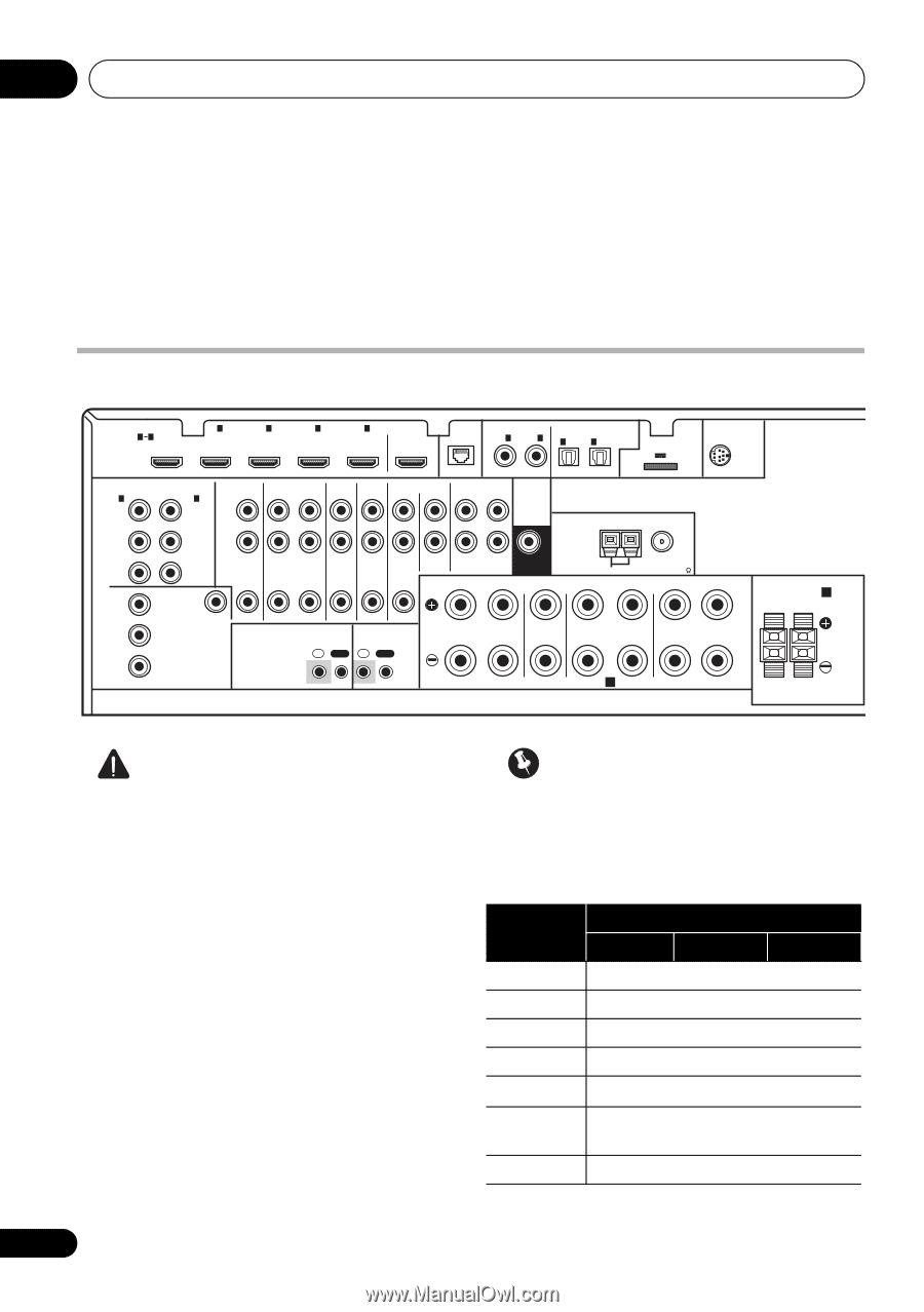
| Rear panel |
14 |
| CAUTION |
14 |
| Important |
14 |
| Determining the speakers’ application |
15 |
| [A] 7.1 channel surround system (Front height) |
15 |
| [B] 7.1 channel surround system (Front wide) |
15 |
| [C] 7.1 channel surround system & Speaker B connection |
15 |
| [D] 5.1 channel surround system & Front Bi-amping connection (High quality surround) |
16 |
| [E] 5.1 channel surround system & ZONE 2 connection (Multi Zone) |
16 |
| Important |
16 |
| Other speaker connection |
16 |
| Placing the speakers |
17 |
| Some tips for improving sound quality |
17 |
| Connecting the speakers |
18 |
| CAUTION |
18 |
| Bare wire connections |
18 |
| 1 Twist exposed wire strands together. |
18 |
| 2 Loosen terminal and insert exposed wire. |
18 |
| 3 Tighten terminal. |
18 |
| 1 Twist exposed wire strands together. |
18 |
| 2 Push open the tabs and insert exposed wire. |
18 |
| 3 Release the tabs. |
18 |
| Banana plug connections |
18 |
| Important |
18 |
| CAUTION |
18 |
| Installing your speaker system |
19 |
| Bi-amping your speakers |
20 |
| CAUTION |
20 |
| Bi-wiring your speakers |
20 |
| . To bi-wire a speaker, connect two speaker cords to the speaker terminal on the receiver. |
20 |
| CAUTION |
20 |
| Selecting the Speaker system |
21 |
| Front height setup |
21 |
| 1 Connect a pair of speakers to the front height speaker terminals. |
21 |
| 2 If necessary, select ‘Normal(SB/FH)’ from the Speaker System menu. |
21 |
| Front wide setup |
21 |
| 1 Connect a pair of speakers to the front height speaker terminals. |
21 |
| 2 Select ‘Normal(SB/FW)’ from the Speaker System menu. |
21 |
| Speaker B setup |
21 |
| 1 Connect a pair of speakers to the front height speaker terminals. |
21 |
| 2 Select ‘Speaker B’ from the Speaker System menu. |
21 |
| Bi-Amping setup |
21 |
| 1 Connect a Bi-amp compatible speakers to the front and surround back speaker terminals. |
21 |
| 2 Select ‘Front Bi-Amp’ from the Speaker System menu. |
21 |
| ZONE 2 setup |
21 |
| 1 Connect a pair of speakers to the surround back speaker terminals. |
21 |
| 2 Select ‘ZONE 2’ from the Speaker System menu. |
21 |
| About the audio connection |
22 |
| Sound signal priority l |
22 |
| HDMI |
22 |
| HD audio |
22 |
| Digital (Coaxial) |
22 |
| Conventional digital audio |
22 |
| Digital (Optical) |
22 |
| RCA (Analog) |
22 |
| (White/Red) |
22 |
| Conventional analog audio |
22 |
| CAUTION |
22 |
| About the video converter |
22 |
| Connecting your TV and playback components |
23 |
| Connecting using HDMI |
23 |
| About HDMI |
24 |
| Connecting your DVD player with no HDMI output |
25 |
| Connecting your TV with no HDMI input |
26 |
| Connecting a satellite/cable receiver or other set-top box |
27 |
| Connecting a HDD/DVD recorder, VCR and other video sources |
27 |
| Connecting other audio components |
28 |
| About the WMA9 Pro decoder |
28 |
| Connecting AM/FM antennas |
29 |
| 1 Pull off the protective shields of both AM antenna wires. |
29 |
| 2 Push open the tabs, then insert one wire fully into each terminal, then release the tabs to secure the AM antenna wires. |
29 |
| 3 Fix the AM loop antenna to the attached stand. |
29 |
| 4 Place the AM antenna on a flat surface and in a direction giving the best reception. |
29 |
| 5 Connect the FM wire antenna into the FM antenna socket. |
29 |
| Connecting external antennas |
29 |
| MULTI-ZONE setup |
30 |
| Making MULTI-ZONE connections |
30 |
| MULTI-ZONE listening options |
30 |
| Basic MULTI-ZONE setup (ZONE 2) |
30 |
| . Connect a separate amplifier to the AUDIO ZONE 2 OUT jacks and a TV monitor to the VIDEO ZONE 2 OUT jack, both on this receiver. |
30 |
| MULTI-ZONE setup using speaker terminals (ZONE 2) |
30 |
| . Connect a TV monitor to the VIDEO ZONE 2 OUT jacks on this receiver. |
30 |
| Connecting Optional Bluetooth ADAPTER |
31 |
| . Switch the receiver into standby and connect Bluetooth ADAPTER to the ADAPTER PORT. |
31 |
| Important |
31 |
| Connecting a SiriusConnect™ Tuner |
31 |
| Connecting to the network through LAN interface |
32 |
| The specifications of a LAN terminal |
32 |
| Connecting an HDMI-equipped component to the front panel input |
32 |
| Connecting an iPod |
33 |
| . Switch the receiver into standby then use the supplied iPod cable to connect your iPod to the iPod/iPhone/USB terminal on the front panel of this receiver. |
33 |
| Connecting a USB device |
33 |
| . Switch the receiver into standby then connect your USB device to the iPod/iPhone/ USB terminal on the front panel of this receiver. |
33 |
| Connecting a USB device for Advanced MCACC output |
34 |
| Connecting an IR receiver |
35 |
| 1 Connect the IR receiver sensor to the IR IN jack on the rear of this receiver. |
35 |
| 2 Connect the IR IN jack of another component to the IR OUT jack on the rear of this receiver to link it to the IR receiver. |
35 |
| Operating other Pioneer components with this unit’s sensor |
35 |
| Important |
35 |
| 1 Decide which component you want to use the remote sensor of. |
35 |
| 2 Connect the CONTROL OUT jack of that component to the CONTROL IN jack of another Pioneer component. |
36 |
| Plugging in the receiver |
36 |
| . Plug the AC power cord into a convenient AC power outlet. |
36 |
| CAUTION |
36 |
| Basic Setup |
37 |
| Changing the OSD display language (OSD Language) |
37 |
| 1 Switch on the receiver and your TV. |
37 |
| 2 Press on the remote control, then press HOME MENU. |
37 |
| 3 Select ‘System Setup’ from the HOME MENU. |
37 |
| 4 Select ‘OSD Language’ from the System Setup menu. |
37 |
| 5 Select the desired language. |
37 |
| 6 Select ‘OK’ to change the language. |
37 |
| Automatically setting up for surround sound (Auto MCACC) |
37 |
| Important |
37 |
| CAUTION |
37 |
| THX® |
37 |
| 1 Switch on the receiver and your TV. |
38 |
| 2 Connect the microphone to the MCACC SETUP MIC jack on the front panel. |
38 |
| 3 Select the parameters you want to set. |
38 |
| 4 Press and then select START. |
39 |
| 5 Follow the instructions on-screen. |
39 |
| 6 Wait for the test tones to finish, then confirm the speaker configuration in the GUI screen. |
39 |
| 7 Make sure ‘OK’ is selected, then press ENTER. |
39 |
| 8 The Auto MCACC Setup procedure is completed and the Home Menu menu reappears automatically. |
39 |
| Problems when using the Auto MCACC Setup |
40 |
| The Input Setup menu |
40 |
| 1 Switch on the receiver and your TV. |
40 |
| 2 Press on the remote control, then press HOME MENU. |
40 |
| 3 Select ‘System Setup’ from the HOME MENU. |
40 |
| 4 Select ‘Input Setup’ from the System Setup menu. |
40 |
| 5 Select the input function that you want to set up. |
40 |
| 6 Select the input(s) to which you’ve connected your component. |
40 |
| 7 When you’re finished, proceed to the settings for other inputs. |
41 |
| 8 When you’re finished, press RETURN. |
41 |
| Input function default and possible settings |
41 |
| Basic playback |
42 |
| Playing a source |
42 |
| 1 Switch on your system components and receiver. |
42 |
| 2 Select the input function you want to play. |
42 |
| 3 Press , then press AUTO/ALC/ DIRECT (AUTO SURR/ALC/STREAM DIRECT) to select ‘AUTO SURROUND’ and start playback of the source. |
42 |
| 4 Use the volume control to adjust the volume level. |
42 |
| Playing a source with HDMI connection |
43 |
| . Use INPUT SELECT to select the HDMI input you’ve connected to (for example, HDMI 1). |
43 |
| Playing an iPod |
43 |
| 1 Switch on the receiver and your TV. |
43 |
| 2 Press iPod USB on the remote control to switch the receiver to the iPod/USB. |
43 |
| Playing back files stored on an iPod |
43 |
| Finding what you want to play |
44 |
| 1 Use i/j to select ‘Music’ from the iPod top menu. |
44 |
| 2 Use i/j to select a category, then press ENTER to browse that category. |
44 |
| 3 Use i/j to browse the selected category (e.g., albums). |
44 |
| 4 Continue browsing until you arrive at what you want to play, then press d to start playback. |
44 |
| Tip |
44 |
| Basic playback controls |
44 |
| Switching the iPod controls |
44 |
| 1 Press iPod CTRL to switch the iPod controls. |
44 |
| 2 Press iPod CTRL again to switch back to the receiver controls. |
44 |
| Tip |
44 |
| Playing a USB device |
45 |
| 1 Switch on the receiver and your TV. |
45 |
| 2 Press iPod USB on the remote control to switch the receiver to the iPod/USB. |
45 |
| Important |
45 |
| Playing back audio files stored on a USB memory device |
45 |
| 1 Use i/j to select ‘Music’ from the USB Top menu. |
45 |
| 2 Use i/j to select a folder, then press ENTER to browse that folder. |
45 |
| 3 Continue browsing until you arrive at what you want to play, then press d to start playback. |
45 |
| Basic playback controls |
45 |
| Playing back photo files stored on a USB memory device |
46 |
| 1 Use i/j to select ‘Photos’ from the USB Top menu. |
46 |
| 2 Use i/j to select a folder, then press ENTER to browse that folder. |
46 |
| 3 Continue browsing until you arrive at what you want to play, then press d to start playback. |
46 |
| Basic playback controls |
46 |
| Slideshow Setup |
46 |
| 1 Use i/j to select ‘Slideshow Setup’ from the USB Top menu. |
46 |
| 2 Select the setting you want. |
46 |
| 3 When you’re finished, press RETURN. |
46 |
| About playable file formats |
47 |
| Music files |
47 |
| Photo files |
47 |
| Listening to the radio |
48 |
| 1 Press TUNER to select the tuner. |
48 |
| 2 Use BAND to change the band (FM or AM), if necessary. |
48 |
| 3 Tune to a station. |
48 |
| Improving FM sound |
48 |
| Using Neural Surround |
48 |
| Tuning directly to a station |
48 |
| 1 Press TUNER to select the tuner. |
48 |
| 2 Use BAND to change the band (FM or AM), if necessary. |
48 |
| 3 Press D.ACCESS (Direct Access). |
48 |
| 4 Use the number buttons to enter the frequency of the radio station. |
48 |
| Saving station presets |
48 |
| 1 Tune to a station you want to memorize. |
48 |
| 2 Press T.EDIT (TUNER EDIT). |
49 |
| 3 Press CLASS to select one of the seven classes, then press PRESET k/l to select the station preset you want. |
49 |
| 4 Press ENTER. |
49 |
| Naming station presets |
49 |
| 1 Choose the station preset you want to name. |
49 |
| 2 Press T.EDIT (TUNER EDIT). |
49 |
| 3 Input the name you want. |
49 |
| Tip |
49 |
| Listening to station presets |
49 |
| 1 Press TUNER to select the tuner. |
49 |
| 2 Press CLASS to select the class in which the station is stored. |
49 |
| 3 Press PRESET k/l to select the station preset you want. |
49 |
| Bluetooth® ADAPTER for Wireless Enjoyment of Music |
50 |
| Wireless music play |
50 |
| Remote control operation |
50 |
| Pairing Bluetooth ADAPTER and Bluetooth wireless technology device |
50 |
| 1 Press , then press Home Menu. |
50 |
| 2 Select ‘System Setup’, then press ENTER. |
50 |
| 3 Select ‘Other Setup’, then press ENTER. |
50 |
| 4 Select ‘Pairing Bluetooth Device’, then press ENTER. |
50 |
| 5 Select the ‘Passcode’ setting you want. |
51 |
| 6 If you selected Others in step 5, enter the passcode. |
51 |
| 7 Follow the instructions displayed on the GUI screen to conduct pairing with the Bluetooth wireless technology device. |
51 |
| 8 Check to see that the Bluetooth ADAPTER is detected by the Bluetooth wireless technology device. |
51 |
| 9 From the Bluetooth wireless technology device list, select Bluetooth ADAPTER and enter the Passcode selected in the step 5. |
51 |
| Listening to Music Contents of Bluetooth wireless technology device with Your System |
51 |
| 1 Press ADAPTER on the remote control to switch the receiver to ADAPTER input mode. |
51 |
| 2 Connect the Bluetooth wireless technology device to the Bluetooth ADAPTER. |
51 |
| 3 Start playback of music contents stored in Bluetooth wireless technology device. |
51 |
| Listening to Internet radio stations |
52 |
| Important |
52 |
| 1 Press NET RADIO to switch to the Internet radio input. |
52 |
| 2 Use i/j to select the Internet radio station to play back, and then press ENTER. |
52 |
| Programming the Internet radio stations |
52 |
| Programming with the GUI screen |
52 |
| 1 Press TOP MENU when Internet Radio station list is displayed. |
52 |
| 2 Use i/j to select the Internet Radio station list screen you wish to edit, and then press ENTER. |
52 |
| 3 Use k/l to select “Edit“. |
52 |
| 4 Enter the URL of the Internet radio station you wish to program. |
53 |
| 5 Enter the title of the Internet radio station. |
53 |
| Programming on the computer screen |
53 |
| 1 Turn on the computer and launch the Internet browser. |
53 |
| 2 In the address bar on the browser, enter the IP address assigned to this receiver. |
53 |
| 3 Enter the title and URL of the Internet radio station you wish to program, then press ‘Update’. |
53 |
| Important |
53 |
| Listening to Satellite Radio |
53 |
| . Press SIRIUS to switch to the SIRIUS input. |
54 |
| Listening to SIRIUS Radio |
54 |
| Selecting channels and browsing by genre |
54 |
| . Press i/j to enter the SIRIUS Channel Guide, then navigate through the channels one at time with i/j, then press ENTER to listen to the SIRIUS radio broadcast. |
54 |
| Tip |
54 |
| Saving channel presets |
55 |
| 1 Select the channel you want to memorize. |
55 |
| 2 Press T.EDIT. |
55 |
| 3 Press CLASS to select one of the seven classes, then press k/l to select the channel preset you want. |
55 |
| 4 Press ENTER. |
55 |
| Tip |
55 |
| Listening to channel presets |
55 |
| 1 Press CLASS to select the class in which the channel is stored. |
55 |
| 2 Press k/l to select the channel preset you want. |
55 |
| Using the SIRIUS Menu |
55 |
| 1 Press TOP MENU. |
55 |
| 2 Use i/j to select a menu item, then press ENTER. |
55 |
| 3 When you’re finished press TOP MENU to return to the reception display. |
55 |
| Listening to your system |
56 |
| Important |
56 |
| Auto playback |
56 |
| . While listening to a source, press , then press AUTO/ALC/DIRECT for auto playback of a source. |
56 |
| Tip |
56 |
| Listening in surround sound |
56 |
| Standard surround sound |
56 |
| . While listening to a source, press , then press STANDARD. |
56 |
| Using the Advanced surround effects |
58 |
| . Press , then press ADV SURR (ADV SURROUND) repeatedly to select a listening mode. |
58 |
| Tip |
58 |
| Listening in stereo |
58 |
| . While listening to a source, press , then press STEREO for stereo playback. |
58 |
| Using Front Stage Surround Advance |
59 |
| . While listening to a source, press , then press STEREO to select Front Stage Surround Advance modes. |
59 |
| Using Stream Direct |
59 |
| . While listening to a source, press , then press AUTO/ALC/DIRECT to select the mode you want. |
59 |
| Selecting MCACC presets |
60 |
| . While listening to a source, press , then press MCACC. |
60 |
| Choosing the input signal |
60 |
| . Press , then press SIGNAL SEL to select the input signal corresponding to the source component. |
60 |
| Better sound using Phase Control |
61 |
| . Press , then press PHASE CTRL (PHASE CONTROL) to switch on phase correction. |
61 |
| Control with HDMI function |
62 |
| Important |
62 |
| Making Control with HDMI connections |
62 |
| Important |
62 |
| HDMI Setup |
63 |
| 1 Press , then press Home Menu. |
63 |
| 2 Select ‘System Setup’, then press ENTER. |
63 |
| 3 Select ‘Other Setup’, then press ENTER. |
63 |
| 4 Select ‘HDMI Setup’, then press ENTER. |
63 |
| 5 Select the ‘Control’ setting you want. |
63 |
| 6 Select the ‘Control Mode’ setting you want. |
63 |
| 7 Select the ‘Display Power Off’ setting you want. |
63 |
| 8 When you’re finished, press HOME MENU. |
63 |
| Before using synchronization |
64 |
| 1 Put all components into standby mode. |
64 |
| 2 Turn the power on for all components, with the power for the TV being turned on last. |
64 |
| 3 Choose the HDMI input to which the TV is connected to this receiver, and see if video output from connected components displays properly on the screen or not. |
64 |
| 4 Check whether the components connected to all HDMI inputs are properly displayed. |
64 |
| About synchronized operations |
64 |
| About connections with a product of a different brand that supports the Control with HDMI function |
65 |
| Setting the PQLS function |
65 |
| . Press , then press PQLS to select PQLS setting. |
65 |
| Cautions on the Control with HDMI function |
66 |
| Using other functions |
67 |
| Setting the Audio options |
67 |
| Important |
67 |
| 1 Press , then press AUDIO PARAMETER. |
67 |
| 2 Use i/j to select the setting you want to adjust. |
67 |
| 3 Use k/l to set it as necessary. |
67 |
| 4 Press RETURN to confirm and exit the menu. |
67 |
| LOW |
69 |
| Setting the Video options |
70 |
| Important |
70 |
| 1 Press , then press VIDEO PARAMETER. |
70 |
| 2 Use i/j to select the setting you want to adjust. |
70 |
| 3 Use k/l to set it as necessary. |
70 |
| 4 Press RETURN to confirm and exit the menu. |
70 |
| Switching the speaker terminal |
72 |
| . Use SPEAKERS on the front panel to select a speaker terminal setting. |
72 |
| Using the MULTI-ZONE controls |
72 |
| 1 Press MULTI-ZONE ON/OFF on the front panel. |
72 |
| 2 Press MULTI-ZONE CONTROL on the front panel. |
72 |
| 3 Use the INPUT SELECTOR dial to select the source for the sub zone. |
72 |
| 4 When Speaker System is set to ZONE 2, use the MASTER VOLUME dial to adjust the volume for the sub zone. |
72 |
| 5 When you’re finished, press MULTI-ZONE CONTROL again to return to the main zone controls. |
73 |
| MULTI-ZONE remote controls |
73 |
| Making an audio or a video recording |
73 |
| 1 Select the source you want to record. |
73 |
| 2 Prepare the source you want to record. |
73 |
| 3 Prepare the recorder. |
73 |
| 4 Start recording, then start playback of the source component. |
74 |
| Reducing the level of an analog signal |
74 |
| . Press , then press A.ATT to switch the input attenuator on or off. |
74 |
| Using the sleep timer |
74 |
| . Press , then press SLEEP repeatedly to set the sleep time. |
74 |
| Dimming the display |
74 |
| . Press , then press DIMMER repeatedly to change the brightness of the front panel display. |
74 |
| Checking your system settings |
74 |
| 1 Press , then press STATUS to check the system settings. |
74 |
| 2 When you’re finished, press STATUS again to switch off the display. |
74 |
| Resetting the system |
75 |
| 1 Switch the receiver into standby. |
75 |
| 2 While holding down ENTER on the front panel, press u STANDBY/ON. |
75 |
| 3 Select ‘RESET’ using PRESET k/l, then press ENTER on the front panel. |
75 |
| 4 Press ENTER to confirm. |
75 |
| Default system settings |
75 |
| Controlling the rest of your system |
76 |
| Operating multiple receivers |
76 |
| 1 Press and hold the R.SETUP, press “4” for three seconds. |
76 |
| 2 Press the number button for the receiver (“Receiver 1” to “Receiver 4”) you wish to operate. |
76 |
| Setting the remote to control other components |
76 |
| Note |
76 |
| Selecting preset codes directly |
77 |
| 1 Press and hold the R.SETUP, press “1” for three seconds. |
77 |
| 2 Press the input function button for the component you want to control. |
77 |
| 3 Use the number buttons to enter the 4- digit preset code. |
77 |
| 4 Repeat steps 2 through 3 for the other components you want to control. |
77 |
| 5 Press R.SETUP to exit the preset setup mode. |
77 |
| Programming signals from other remote controls |
77 |
| 1 Press and hold the R.SETUP, press “2” for three seconds. |
77 |
| 2 Press the input function button for the component you want to control. |
77 |
| 3 Point the two remote controls towards each other, then press the button that will be doing the learning on this receiver’s remote control. |
78 |
| 4 Press the corresponding button on the other remote control that is sending (teaching) the signal to this receiver’s remote control. |
78 |
| 5 To program additional signals for the current component repeat steps 3 and 4. |
78 |
| 6 Press R.SETUP to exit the programming mode. |
78 |
| Erasing one of the remote control button settings |
78 |
| 1 Press and hold the R.SETUP, press “7” for three seconds. |
78 |
| 2 Press the input function button corresponding to the command to be erased, then press ENTER. |
78 |
| 3 Press and hold the button to be erased for three seconds. |
78 |
| 4 Repeat step 3 to erase other buttons. |
78 |
| 5 Press R.SETUP to exit the erasing mode. |
78 |
| Erasing all learnt settings that are in one input function |
79 |
| 1 Press and hold the R.SETUP, press “9” for three seconds. |
79 |
| 2 Press and hold the input function button corresponding to the command to be erased for three seconds. |
79 |
| Direct function |
79 |
| 1 Press and hold the R.SETUP, press “5” for three seconds. |
79 |
| 2 Press the input function button for the component you want to control. |
79 |
| 3 Press “1” (On) or “0” (Off) to switch direct function. |
79 |
| 4 Press R.SETUP to exit the setup. |
79 |
| Multi operation and System off |
80 |
| Programming a Multi operation or a shutdown sequence |
80 |
| 1 Press and hold the R.SETUP, press “3” for three seconds. |
80 |
| 2 Press the input function button (or u SOURCE button). |
80 |
| 3 If necessary, press the input function button for the component whose command you want to input. |
80 |
| 4 Select the button for the command you want to input. |
80 |
| 5 Repeat steps 3 to 4 to program a sequence of up to five commands. |
81 |
| Using multi operations |
81 |
| 1 Press MULTI OPERATION. |
81 |
| 2 Within five seconds, press an input function button that has been set up with a multi operation. |
81 |
| Using System off |
81 |
| 1 Press MULTI OPERATION. |
81 |
| 2 Within five seconds, press u SOURCE. |
81 |
| Erasing all the settings for the multi- operation |
81 |
| 1 Press and hold the R.SETUP, press “8” for three seconds. |
81 |
| 2 Press the input function button containing the program you want to cancel or the u SOURCE button for three seconds. |
81 |
| Resetting the remote control presets |
82 |
| 1 Press and hold the R.SETUP, press “0” for three seconds. |
82 |
| 2 Press and hold the ENTER button for three seconds. |
82 |
| Default preset codes |
82 |
| BD |
82 |
| 2160 |
82 |
| DVD |
82 |
| 2158 |
82 |
| DVR/BDR |
82 |
| 2150 |
82 |
| HDMI |
82 |
| 2159 |
82 |
| TV |
82 |
| 0116 |
82 |
| CD |
82 |
| 5066 |
82 |
| TV CTRL |
82 |
| 0116 |
82 |
| Controls the components |
82 |
| b. Controls for SACD. |
84 |
| c. Controls for MD. |
84 |
| The Advanced MCACC menu |
85 |
| Making receiver settings from the Advanced MCACC menu |
85 |
| 1 Switch on the receiver and your TV. |
85 |
| 2 Press on the remote control, then press HOME MENU. |
85 |
| 3 Select ‘Advanced MCACC’ from the HOME MENU, then press ENTER. |
85 |
| 4 Select the setting you want to adjust. |
85 |
| Automatic MCACC (Expert) |
86 |
| Important |
86 |
| CAUTION |
86 |
| 1 Select ‘Auto MCACC’ from the Advanced MCACC menu, then press ENTER. |
86 |
| 2 Select the parameters you want to set. |
86 |
| 3 Connect the microphone to the MCACC SETUP MIC jack on the front panel. |
87 |
| 4 When you’re finished setting the options, select START then press ENTER. |
87 |
| 5 Follow the instructions on-screen. |
87 |
| 6 Wait for the Auto MCACC Setup to finish outputting test tones. |
88 |
| 7 If necessary, confirm the speaker configuration in the GUI screen. |
88 |
| 8 Make sure ‘OK’ is selected, then press ENTER.2 |
88 |
| 9 The Auto MCACC Setup procedure is completed and the Advanced MCACC menu reappears automatically. |
88 |
| Manual MCACC setup |
89 |
| CAUTION |
89 |
| Important |
89 |
| 1 Select ‘Manual MCACC’ from the Advanced MCACC menu. |
90 |
| 2 Select the setting you want to adjust. |
90 |
| Fine Channel Level |
90 |
| 1 Select ‘Fine Channel Level’ from the Manual MCACC setup menu. |
90 |
| 2 Adjust the level of the left channel. |
90 |
| 3 Select each channel in turn and adjust the levels (+/-12.0 dB) as necessary. |
90 |
| 4 When you’re finished, press RETURN. |
90 |
| Fine Speaker Distance |
90 |
| 1 Select ‘Fine SP Distance’ from the Manual MCACC setup menu. |
90 |
| 2 Adjust the distance of the left channel from the listening position. |
90 |
| 3 Select each channel in turn and adjust the distance as necessary. |
91 |
| 4 When you’re finished, press RETURN. |
91 |
| Standing Wave |
91 |
| 1 Select ‘Standing Wave’ from the Manual MCACC setup menu. |
91 |
| 2 Adjust the parameters for the Standing Wave Control. |
91 |
| 3 When you’re finished, press RETURN. |
92 |
| Acoustic Calibration EQ Adjust |
92 |
| 1 Select ‘EQ Adjust’ from the Manual MCACC setup menu. |
92 |
| 2 Select the channel(s) you want and adjust to your liking. |
92 |
| Tip |
92 |
| 3 When you’re finished, press RETURN. |
92 |
| Acoustic Calibration EQ Professional |
92 |
| How to use Acoustic Calibration EQ Professional |
92 |
| Using Acoustic Calibration EQ Professional |
93 |
| 1 Select ‘EQ Professional’, then press ENTER. |
93 |
| 2 Select an option and press ENTER. |
93 |
| 3 If you selected ‘Reverb Measurement’, select EQ ON or OFF, and then START. |
93 |
| 4 If you selected ‘Reverb View’, you can check the reverb characteristics for each channel. Press RETURN when you’re done. |
94 |
| 5 If ‘Advanced EQ Setup’ is selected, select the MCACC memory to be stored, then enter the desired time setting for calibration, and then select START. |
94 |
| Checking MCACC Data |
95 |
| 1 Press , then press HOME MENU. |
95 |
| 2 Select ‘MCACC Data Check’ from the HOME MENU. |
95 |
| 3 Select the setting you want to check. |
95 |
| 4 Press RETURN to go back to MCACC Data Check menu, repeating steps 2 and 3 to check other settings. |
95 |
| 5 When you’re finished, press RETURN. |
95 |
| Speaker Setting |
95 |
| 1 Select ‘Speaker Setting’ from the MCACC Data Check menu. |
95 |
| 2 Select the channel you want to check. |
95 |
| Channel Level |
95 |
| 1 Select ‘Channel Level’ from the MCACC Data Check menu. |
95 |
| 2 When ‘MCACC’ is highlighted, use k/l to select the MCACC preset you want to check. |
95 |
| Speaker Distance |
95 |
| 1 Select ‘Speaker Distance’ from the MCACC Data Check menu. |
95 |
| 2 When ‘MCACC’ is highlighted, use k/l to select the MCACC preset you want to check. |
95 |
| Standing Wave |
96 |
| 1 Select ‘Standing Wave’ from the MCACC Data Check menu. |
96 |
| 2 When ‘Filter Channel’ is highlighted, use i/j to select the channel for which you want to check standing wave control. |
96 |
| 3 Press k to highlight ‘MCACC’, then use i/j to select the MCACC preset you want to check. |
96 |
| Acoustic Cal EQ |
96 |
| 1 Select ‘Acoustic Cal EQ’ from the MCACC Data Check menu. |
96 |
| 2 When ‘Ch’ is highlighted, use i/j to select the channel. |
96 |
| 3 Press k to highlight ‘MCACC’, then use i/j to select the MCACC preset you want to check. |
96 |
| Output MCACC data |
96 |
| 1 Select ‘Output MCACC data’ from MCACC Data Check menu. |
96 |
| 2 Connect your USB device to the USB terminal on the front panel, then select “OK”. |
96 |
| 3 When you’re finished, press RETURN. |
97 |
| Data Management |
97 |
| 1 Press , then press HOME MENU. |
97 |
| 2 Select ‘Data Management’ from the HOME MENU. |
97 |
| 3 Select the setting you want to adjust. |
97 |
| Renaming MCACC presets |
97 |
| 1 Select ‘Memory Rename’ from the Data Management setup menu. |
97 |
| 2 Select the MCACC preset you want to rename, then select an appropriate preset name. |
97 |
| 3 Repeat for as many MCACC presets as necessary, then press RETURN when you’re finished. |
97 |
| Copying MCACC preset data |
97 |
| 1 Select ‘MCACC Memory Copy’ from the Data Management setup menu. |
97 |
| 2 Select the setting you want to copy. |
97 |
| 3 Select the MCACC preset you’ll be copying the settings ‘From’, then specify where you want to copy them (‘To’). |
98 |
| 4 Select ‘OK’ to confirm and copy the settings. |
98 |
| Clearing MCACC presets |
98 |
| 1 Select ‘MCACC Memory Clear’ from the Data Management setup menu. |
98 |
| 2 Select the MCACC preset you want to clear. |
98 |
| 3 Select ‘OK’ to confirm and clear the preset. |
98 |
| The system and the other setup |
99 |
| Making receiver settings from the System Setup menu |
99 |
| 1 Switch on the receiver and your TV. |
99 |
| 2 Press , then press HOME MENU. |
99 |
| 3 Select ‘System Setup’ from the HOME MENU, then press ENTER. |
99 |
| 4 Select the setting you want to adjust. |
99 |
| Manual speaker setup |
99 |
| CAUTION |
99 |
| 1 Select ‘Manual SP Setup’, then press ENTER. |
99 |
| 2 Select the setting you want to adjust. |
99 |
| 3 Make the adjustments necessary for each setting, pressing RETURN to confirm after each screen. |
100 |
| Speaker system setting |
100 |
| 1 Select ‘Speaker System’ from the Manual SP Setup menu. |
100 |
| 2 Select the speaker system setting. |
100 |
| 3 If you selected in Step 2, any one of Normal(SB/FH), Normal(SB/FW), or Speaker B, select the placement of the surround speakers. |
100 |
| 4 When ‘Setting Change?’ is displayed, select Yes. |
100 |
| Speaker Setting |
101 |
| 1 Select ‘Speaker Setting’ from the Manual SP Setup menu. |
101 |
| 2 Choose the set of speakers that you want to set, then select a speaker size. |
101 |
| 3 Select ‘X. OVER’ and set the crossover frequency. |
102 |
| 4 When you’re finished, press RETURN. |
102 |
| Channel Level |
102 |
| 1 Select ‘Channel Level’ from the Manual SP Setup menu. |
102 |
| 2 Adjust the level of each channel using k/ l. |
102 |
| 3 When you’re finished, press RETURN. |
102 |
| Tip |
102 |
| Speaker Distance |
102 |
| 1 Select ‘Speaker Distance’ from the Manual SP Setup menu. |
103 |
| 2 Adjust the distance of each speaker using k/l. |
103 |
| 3 When you’re finished, press RETURN. |
103 |
| Tip |
103 |
| X-Curve |
103 |
| 1 Select ‘X-Curve’ from the Manual SP Setup menu. |
103 |
| 2 Choose the X-Curve setting you want. |
103 |
| 3 When you’re finished, press RETURN. |
103 |
| Network Setup menu |
103 |
| 1 Press on the remote control, then press HOME MENU. |
103 |
| 2 Select ‘System Setup’ from the HOME MENU. |
103 |
| 3 Select ‘Network Setup’ from the System Setup. |
103 |
| 4 Select the setting you want to adjust. |
103 |
| IP address/Proxy setting |
103 |
| Tip |
104 |
| 1 Select ‘IP Address, Proxy’ from the Network Setup menu. |
104 |
| 2 Select the DHCP setting you want. |
104 |
| 3 Enter the IP Address, Subnet Mask, Default Gateway, Primary DNS Server and Secondary DNS Server. |
104 |
| 4 Select ‘OFF’ or ‘ON’ for the Enable Proxy Server setting to deactivate or activate the proxy server. |
104 |
| 5 Enter the address of your proxy server or the domain name. |
104 |
| 6 Enter the port number of your proxy server. |
104 |
| 7 Select ‘OK’ to confirm the IP Address/ Proxy setup. |
104 |
| Checking the MAC address |
104 |
| . Select ‘Information’ from the Network Setup menu. |
104 |
| The Other Setup menu |
105 |
| 1 Press on the remote control, then press HOME MENU. |
105 |
| 2 Select ‘System Setup’ from the HOME MENU. |
105 |
| 3 Select ‘Other Setup’, then press ENTER. |
105 |
| 4 Select the setting you want to adjust. |
105 |
| 5 Make the adjustments necessary for each setting, pressing RETURN to confirm after each screen. |
105 |
| Volume Setup |
105 |
| 1 Select ‘Volume Setup’ from the Other Setup menu. |
105 |
| 2 Select the Power ON Level setting you want. |
105 |
| 3 Select the Volume Limit setting you want. |
105 |
| 4 Select the Mute Level setting you want. |
105 |
| 5 When you’re finished, press RETURN. |
105 |
| Remote Control Mode Setup |
106 |
| 1 Select ‘Remote Control Mode Setup’ from the Other Setup menu. |
106 |
| 2 Select the Remote Control Mode setting you want. |
106 |
| 3 Select “OK” to change the remote control mode. |
106 |
| 4 Follow the instructions on the screen to change the remote control’s setting. |
106 |
| 5 When you’re finished, press RETURN. |
106 |
| Flicker Reduction Setup |
106 |
| 1 Select ‘Flicker Reduction Setup’ from the Other Setup menu. |
106 |
| 2 Select the Flicker Reduction setting you want. |
106 |
| 3 When you’re finished, press RETURN. |
106 |
| Additional information |
107 |
| Troubleshooting |
107 |
| Note |
107 |
| Power |
107 |
| No sound |
108 |
| Other audio problems |
109 |
| The Bluetooth wireless technology device cannot be connected or operated. Sound from the Bluetooth wireless technology device is not emitted or the sound is interrupted. |
111 |
| . Check that no object that emits electromagnetic waves in the 2.4 GHz band (microwave oven, wireless LAN device or Bluetooth wi... |
111 |
| . Check that the Bluetooth wireless technology device is not too far from the unit and that obstructions are not set between the... |
111 |
| . Check that the Bluetooth ADAPTER and the ADAPTER PORT of the unit are correctly connected. |
111 |
| . The Bluetooth wireless technology device may not be set to the communication mode supporting the Bluetooth wireless technology. Check the setting of the Bluetooth wireless technology device. |
111 |
| . Check that pairing is correct. The pairing setting was deleted from this unit or the Bluetooth wireless technology device. Reset the pairing. |
111 |
| . Check that the profile is correct. Use a Bluetooth wireless technology device that supports A2DP profile and AVRCP profile. |
111 |
| Video |
111 |
| Settings |
112 |
| Professional Calibration EQ graphical output |
113 |
| Display |
113 |
| Remote control |
114 |
| HDMI |
115 |
| Important information regarding the HDMI connection |
116 |
| Configuration A |
116 |
| Note |
116 |
| Configuration B |
116 |
| Note |
116 |
| USB interface |
117 |
| Internet radio |
118 |
| SIRIUS radio messages |
118 |
| About iPod |
119 |
| About SIRIUS |
119 |
| Surround sound formats |
120 |
| Dolby |
120 |
| DTS |
120 |
| Windows Media Audio 9 Professional |
120 |
| Auto Surround, ALC and Stream Direct with different input signal formats |
121 |
| Stereo (2 channel) signal formats |
121 |
| Multichannel signal formats |
121 |
| Preset code list |
122 |
| Important |
122 |
| TV |
122 |
| TV |
122 |
| DVD |
123 |
| BD |
124 |
| DVR (BDR, HDR) |
124 |
| VCR |
124 |
| Satellite Set Top Box |
125 |
| Satellite Set Top Box (SAT/PVR Combination) |
125 |
| Cable Set Top Box |
126 |
| Cable Set Top Box (Cable/PVR Combination) |
126 |
| CD |
126 |
| CD-R |
126 |
| Laser Disc Player |
126 |
| Cassete Deck |
126 |
| Digital Tape |
126 |
| MD |
126 |
| Specifications |
127 |
| Amplifier section |
127 |
| Audio Section |
127 |
| Tuner Section |
127 |
| Video Section |
127 |
| Digital In/Out Section |
127 |
| Integrated control section |
127 |
| Miscellaneous |
127 |
| Furnished Parts Number |
127 |
| Note |
127 |
| Cleaning the unit |
128 |
| 100825_VSX-1020_Sp.book.pdf |
132 |
| Organigrama de ajustes del receptor |
135 |
| Los colores de los pasos indican lo siguiente: |
135 |
| 1 Antes de comenzar |
135 |
| j |
135 |
| 2 Determinación de la aplicación de los altavoces (página 15) |
135 |
| j |
135 |
| 3 Conexión de los altavoces |
135 |
| j |
135 |
| 4 Conexión de los componentes |
135 |
| j |
135 |
| 5 Encendido |
135 |
| j |
135 |
| 6 Cambio del idioma de la OSD (OSD Language) (página 37) |
135 |
| j |
135 |
| 7 Ajustes de altavoces MCACC |
135 |
| j |
135 |
| 8 El menú Input Setup (página 40) |
135 |
| j |
135 |
| 9 Reproducción básica (página 42) |
135 |
| j |
135 |
| 10 Ajuste de la calidad del sonido y de la imagen según se quiera |
135 |
| j |
135 |
| 11 Otras configuraciones y ajustes opcionales |
135 |
| j |
135 |
| 12 Máximo provecho del mando a distancia |
135 |
| Antes de comenzar |
136 |
| Comprobación del contenido de la caja |
136 |
| Instalación del receptor |
136 |
| Colocación de las pilas |
136 |
| PRECAUCIÓN |
136 |
| Controles e indicadores |
137 |
| Panel frontal |
137 |
| 1 Dial INPUT SELECTOR |
137 |
| 2 u STANDBY/ON |
137 |
| 3 SPEAKERS |
137 |
| 4 Sensor del mando a distancia |
137 |
| 5 Controles MULTI-ZONE |
137 |
| 6 Pantalla de visualización de caracteres |
137 |
| 7 Indicadores |
137 |
| 8 Teclas de sintonización |
137 |
| 9 Dial MASTER VOLUME |
137 |
| 10 Conector PHONES |
137 |
| 11 Botones Listening mode |
138 |
| 12 iPod iPhone DIRECT CONTROL |
138 |
| 13 Conector MCACC SETUP MIC |
138 |
| 14 Terminales iPod/iPhone/USB |
138 |
| 15 Conector de entrada HDMI |
138 |
| Pantalla |
138 |
| 1 Indicadores del SIGNAL |
138 |
| 2 Indicadores de formato de programa |
138 |
| 3 Indicadores de formato digital |
138 |
| 4 MULTI-ZONE |
138 |
| 5 SOUND |
139 |
| 6 S.RTRV |
139 |
| 7 Indicadores de modo de audición |
139 |
| 8 (PHASE CONTROL) |
139 |
| 9 Indicadores de señal analógica |
139 |
| 10 Indicadores del sintonizador |
139 |
| 11 |
139 |
| 12 Nivel de volumen principal |
139 |
| 13 Indicadores de función de entrada |
139 |
| 14 Indicadores de desplazamiento |
139 |
| 15 Indicadores de altavoces |
139 |
| 16 SLEEP |
139 |
| 17 Indicadores de formato de descodificación de matriz |
139 |
| 18 Pantalla de visualización de caracteres |
139 |
| 19 Indicador de modo de control remoto |
139 |
| Mando a distancia |
140 |
| El mando a distancia presenta un código de colores según el control del componente utilizando el siguiente sistema: |
140 |
| 1 u RECEIVER |
140 |
| 2 MULTI OPERATION - Se utiliza para realizar operaciones múltiples (página 80). |
140 |
| 3 Botones de función de entrada |
140 |
| 4 ZONE 2 |
140 |
| 5 Botones TV CONTROL |
140 |
| 6 Controles del receptor |
140 |
| 7 i/j/k/l, ENTER |
140 |
| 8 Controles del receptor |
141 |
| 9 Controles del MODO DE AUDICIÓN |
141 |
| 10 LED de mando a distancia |
141 |
| 11 TV CTRL |
141 |
| 12 |
141 |
| 13 MASTER VOLUME +/- |
141 |
| 14 MUTE |
141 |
| Alcance del mando a distancia |
141 |
| Conexión del equipo |
142 |
| Panel trasero |
142 |
| PRECAUCIÓN |
142 |
| Importante |
142 |
| COAX-1 |
142 |
| IN 1 |
142 |
| (BD) |
142 |
| OPT-1 |
142 |
| OPT-2 |
142 |
| IN 2 |
142 |
| (HDMI-1-4) |
142 |
| (HDMI-5) |
142 |
| COAX-2 |
142 |
| Determinación de la aplicación de los altavoces |
143 |
| [A] Sistema de sonido envolvente de 7.1 canales (delantero con efecto de altura) |
143 |
| *Ajuste por defecto |
143 |
| [B] Sistema de sonido envolvente de 7.1 canales (delantero de amplitud) |
143 |
| [C] Sistema de sonido envolvente de 7.1 canales y conexión de Speaker B |
143 |
| [D] Sistema de sonido envolvente de 5.1 canales y conexión de biamplificación delantera (sonido envolvente de alta calidad) |
144 |
| [E] Sistema de sonido envolvente de 5.1 canales y ZONE 2 (Multi Zone) |
144 |
| Importante |
144 |
| Conexión de otros altavoces |
144 |
| Disposición de los altavoces |
145 |
| Algunos consejos para mejorar la calidad del sonido |
145 |
| Conexión de los altavoces |
146 |
| PRECAUCIÓN |
146 |
| Conexiones de cables pelados |
146 |
| Terminales de altavoces A: |
146 |
| 1 Trence los hilos expuestos del cable. |
146 |
| 2 Afloje el terminal e inserte el hilo expuesto. |
146 |
| 3 Apriete el terminal. |
146 |
| Terminales de altavoces B: |
146 |
| 1 Trence los hilos expuestos del cable. |
146 |
| 2 Empuje para abrir las pestañas e introduzca los hilos expuestos del cable. |
146 |
| 3 Suelte la pestañas. |
146 |
| Conexiones con clavijas tipo banana |
146 |
| (Sólo terminales de Altavoz A) |
146 |
| Importante |
146 |
| PRECAUCIÓN |
146 |
| Instalación del sistema de altavoces |
147 |
| Biamplificación de los altavoces |
148 |
| PRECAUCIÓN |
148 |
| Bicableado de los altavoces |
148 |
| . Para bicablear un altavoz, conecte dos cables de altavoz al terminal de altavoces del receptor. |
148 |
| PRECAUCIÓN |
148 |
| Selección del sistema de altavoces |
149 |
| Configuración delantera con efecto de altura |
149 |
| *Ajuste por defecto |
149 |
| 1 Conecte un par de altavoces a las terminales de altavoces delanteros con efecto de altura. |
149 |
| 2 Si es preciso, seleccione ‘Normal(SB/FH)’ en el menú Speaker System. |
149 |
| Configuración delantera de amplitud |
149 |
| 1 Conecte un par de altavoces a las terminales de altavoces delanteros con efecto de altura. |
149 |
| 2 Seleccione ‘Normal(SB/FW)’ desde el menú Speaker System. |
149 |
| Configuración de altavoces B |
149 |
| 1 Conecte un par de altavoces a las terminales de altavoces delanteros con efecto de altura. |
149 |
| 2 Seleccione ‘Speaker B’ desde el menú Speaker System. |
149 |
| Configuración de biamplificación |
149 |
| 1 Conecte altavoces compatibles con biamplificación a los terminales de altavoces delanteros y de altavoces de sonido traseros. |
149 |
| 2 Seleccione ‘Front Bi-Amp’ desde el menú Speaker System. |
149 |
| Configuración de ZONE 2 |
149 |
| 1 Conecte un par de altavoces a los terminales de altavoces de sonido envolvente traseros. |
149 |
| 2 Seleccione ‘ZONE 2’ desde el menú Speaker System. |
149 |
| Acerca de la conexión de audio |
150 |
| HDMI |
150 |
| Audio HD |
150 |
| Digital (Coaxial) |
150 |
| Audio digital convencional |
150 |
| Digital (Óptico) |
150 |
| RCA (Analógico) |
150 |
| (Blanco/Rojo) |
150 |
| Audio analógico convencional |
150 |
| PRECAUCIÓN |
150 |
| Acerca del convertidor de vídeo |
150 |
| Conexión a su televisor y componentes de reproducción |
151 |
| Conexión mediante HDMI |
151 |
| Acerca de HDMI |
152 |
| HDMI, el logotipo HDMI y High-Definition Multimedia Interface son marcas comerciales o marcas registradas de HDMI Licensing, LLC en los Estados Unidos de América y en otros países. |
152 |
| “x.v.Color” y el logotipo x.v.Color son marcas de fábrica de Sony Corporation. |
152 |
| Conexión de su reproductor DVD sin salida de HDMI |
153 |
| Conexión a su televisor sin entrada HDMI |
154 |
| Conexión de un receptor satélite/por cable o de otro tipo |
155 |
| Conexión a una grabadora HDD/ DVD, grabadora de vídeo y otras fuentes de vídeo |
155 |
| Conexión de otros componentes de audio |
156 |
| Acerca del descodificador WMA9 Pro |
156 |
| Conexión de antenas de AM/FM |
157 |
| 1 Retire los protectores de los dos hilos del cable de antena de AM. |
157 |
| 2 Abra las pestañas, inserte un cable completamente en cada terminal y, a continuación, suelte las pestañas para fijar los cables de antena AM. |
157 |
| 3 Coloque la antena de cuadro AM en el soporte fijado. |
157 |
| 4 Coloque la antena AM en una superficie plana y en una dirección que ofrezca la mejor recepción. |
157 |
| 5 Conecte el cable de antena FM en la toma de antena FM. |
157 |
| Conexión de antenas externas |
157 |
| Configuración MULTI-ZONE |
158 |
| Conexiones MULTI-ZONA |
158 |
| Opciones de escucha MULTI-ZONA |
158 |
| Configuración MULTI-ZONE básica (ZONE 2) |
158 |
| . Conecte un amplificador independiente a los conectores AUDIO ZONE 2 OUT y un monitor de TV al conector VIDEO ZONE 2 OUT, situados ambos en este receptor. |
158 |
| Configuración MULTI-ZONE utilizando terminales de altavoces (ZONE 2) |
158 |
| . Conecte un monitor de TV a los conectores VIDEO ZONE 2 OUT de este receptor. |
158 |
| Conexión del ADAPTADOR Bluetooth opcional |
159 |
| . Ponga el receptor en espera y conecte el ADAPTADOR Bluetooth al ADAPTER PORT. |
159 |
| Importante |
159 |
| Conexión de un sintonizador SiriusConnect™ |
159 |
| Conexión a la red mediante la interfaz LAN |
160 |
| Las especificaciones de un terminal LAN |
160 |
| Conexión de un componente equipado con HDMI a la entrada del panel frontal |
160 |
| Conexión de un iPod |
161 |
| . Ponga el receptor en el modo de espera y luego use el cable del iPod suministrado para conectar el iPod al terminal iPod/iPhone/USB del panel frontal de este receptor. |
161 |
| Conexión de un dispositivo USB |
161 |
| . Ponga el receptor en espera y luego conecte su aparato USB al terminal iPod/ iPhone/USB del panel frontal de este receptor. |
161 |
| Conexión de un dispositivo USB para Advanced MCACC |
162 |
| Conexión de un receptor de infrarrojos |
163 |
| 1 Conecte el sensor del receptor de infrarrojos a la toma IR IN en la parte trasera del receptor. |
163 |
| 2 Conecte el conector IR IN de otro componente al conector IR OUT de la parte posterior de este receptor para conectarlo al receptor IR. |
163 |
| Utilización de otros componentes Pioneer con el sensor de esta unidad |
163 |
| Importante |
163 |
| 1 Elija el componente cuyo sensor de mando a distancia desea usar. |
163 |
| 2 Conecte el conector CONTROL OUT de ese componente al conector CONTROL IN de otro componente Pioneer. |
164 |
| Conexión del receptor |
164 |
| . Enchufe el cable de alimentación de CA en una toma de CA. |
164 |
| PRECAUCIÓN |
164 |
| Configuración básica |
165 |
| Cambio del idioma de la OSD (OSD Language) |
165 |
| 1 Encienda el receptor y su televisor. |
165 |
| 2 Pulse en el mando a distancia y, a continuación, pulse HOME MENU. |
165 |
| 3 Seleccione ‘System Setup’ desde HOME MENU. |
165 |
| 4 Seleccione ‘OSD Language’ desde el menú System Setup. |
165 |
| 5 Seleccione el idioma deseado. |
165 |
| 6 Seleccione ‘OK’ para cambiar el idioma. |
165 |
| Configuración automática para sonido envolvente (Auto MCACC) |
165 |
| Importante |
165 |
| PRECAUCIÓN |
165 |
| THX® |
165 |
| 1 Encienda el receptor y su televisor. |
166 |
| 2 Conecte el micrófono al conector MCACC SETUP MIC del panel frontal. |
166 |
| 3 Seleccione los parámetros que quiera establecer. |
166 |
| 4 Pulse y luego seleccione START. |
166 |
| 5 Siga las instrucciones que aparecen en la pantalla. |
166 |
| 6 Espere a que terminen los tonos de prueba para confirmar la configuración de los altavoces en la pantalla GUI. |
167 |
| 7 Asegúrese de que la opción ‘OK’ esté seleccionada; luego, pulse ENTER. |
167 |
| 8 El procedimiento Auto MCACC Setup se completa y el menú Home Menu reaparece automáticamente. |
167 |
| Problemas al utilizar la configuración automática de MCACC |
168 |
| El menú Input Setup |
168 |
| 1 Encienda el receptor y su televisor. |
168 |
| 2 Pulse en el mando a distancia y, a continuación, pulse HOME MENU. |
168 |
| 3 Seleccione ‘System Setup’ desde HOME MENU. |
168 |
| 4 Seleccione ‘Input Setup’ desde el menú System Setup. |
168 |
| 5 Seleccione la función de entrada que desea configurar. |
168 |
| 6 Seleccione la(s) entrada(s) a las que ha conectado el componente. |
168 |
| 7 Cuando haya terminado, haga los ajustes para las otras entradas. |
169 |
| 8 Cuando termine, pulse RETURN. |
169 |
| Valor por defecto de la función de entrada y posibles ajustes |
169 |
| COAX-1 |
169 |
| k |
169 |
| IN 1 |
169 |
| OPT-1 |
169 |
| ka |
169 |
| OPT-2 |
169 |
| ka |
169 |
| IN 2 |
169 |
| ka |
169 |
| (HDMI-1) |
169 |
| (HDMI-2) |
169 |
| (HDMI-3) |
169 |
| (HDMI-4) |
169 |
| (HDMI-5) |
169 |
| COAX-2 |
169 |
| Reproducción básica |
170 |
| Reproducción de una fuente |
170 |
| 1 Encienda los componentes del sistema y el receptor. |
170 |
| 2 Seleccione la función de entrada que desea reproducir. |
170 |
| 3 Pulse y luego AUTO/ALC/ DIRECT (AUTO SURR/ALC/STREAM DIRECT) para seleccionar ‘AUTO SURROUND’ y empezar a reproducir la fuente. |
170 |
| 4 Utilice el control de volumen para ajustar el nivel de volumen. |
170 |
| Reproducción de una fuente con conexión HDMI |
171 |
| . Utilice INPUT SELECT para seleccionar la entrada HDMI a la que ha hecho la conexión (por ejemplo, HDMI 1). |
171 |
| Reproducción de un iPod |
171 |
| 1 Encienda el receptor y su televisor. |
171 |
| 2 Pulse iPod USB en el mando a distancia para poner el receptor en el modo iPod/USB. |
171 |
| Reproducción de archivos guardados en un iPod |
171 |
| Búsqueda del elemento que desea reproducir |
172 |
| 1 Utilice i/j para seleccionar ‘Music’ en el menú inicial del iPod. |
172 |
| 2 Utilice i/j para seleccionar una categoría y, a continuación, pulse ENTER para buscar esa categoría. |
172 |
| 3 Utilice i/j para examinar la categoría seleccionada (p. ej., álbumes). |
172 |
| 4 Siga buscando hasta que encuentre lo que quiere reproducir. A continuación, pulse d para iniciar la reproducción. |
172 |
| Sugerencia |
172 |
| Controles de reproducción básica |
172 |
| Cambio de los controles del iPod |
172 |
| 1 Pulse iPod CTRL para cambiar los controles del iPod. |
172 |
| 2 Pulse de nuevo iPod CTRL para volver a los controles del receptor. |
172 |
| Sugerencia |
172 |
| Reproducción de un aparato USB |
172 |
| 1 Encienda el receptor y su televisor. |
172 |
| 2 Pulse iPod USB en el mando a distancia para poner el receptor en el modo iPod/USB. |
173 |
| Importante |
173 |
| Reproducción de archivos de audio guardados en un dispositivo de memoria USB |
173 |
| 1 Utilice i/j para seleccionar ‘Music’ en el menú USB Top. |
173 |
| 2 Utilice i/j para seleccionar una carpeta y luego pulse ENTER para examinar esa carpeta. |
173 |
| 3 Siga desplazándose hasta llegar al elemento que desea reproducir y, a continuación, pulse d para iniciar la reproducción. |
173 |
| Controles de reproducción básica |
173 |
| Reproducción de archivos de fotos guardados en un dispositivo de memoria USB |
174 |
| 1 Utilice i/j para seleccionar ‘Photos’ en el menú USB Top. |
174 |
| 2 Utilice i/j para seleccionar una carpeta y luego pulse ENTER para examinar esa carpeta. |
174 |
| 3 Siga desplazándose hasta llegar al elemento que desea reproducir y, a continuación, pulse d para iniciar la reproducción. |
174 |
| Controles de reproducción básica |
174 |
| Configuración de presentación de diapositivas |
174 |
| 1 Utilice i/j para seleccionar ‘Slideshow Setup’ en el menú USB Top. |
174 |
| 2 Seleccione la opción que quiera. |
174 |
| 3 Cuando termine, pulse RETURN. |
174 |
| Acerca de los formatos de archivo reproducibles |
175 |
| Archivos de música |
175 |
| Archivos de fotos |
175 |
| Recepción de radio |
176 |
| 1 Pulse TUNER para seleccionar el sintonizador. |
176 |
| 2 Utilice BAND para cambiar la banda (FM o AM), si es necesario. |
176 |
| 3 Sintonice una emisora. |
176 |
| Mejora del sonido de FM |
176 |
| Uso de Neural Surround |
176 |
| Sintonización directa de una emisora |
176 |
| 1 Pulse TUNER para seleccionar el sintonizador. |
176 |
| 2 Utilice BAND para cambiar la banda (FM o AM), si es necesario. |
176 |
| 3 Pulse D.ACCESS (acceso directo). |
176 |
| 4 Utilice los botones numéricos para introducir la frecuencia de la emisora de radio. |
176 |
| Presintonización de emisoras |
177 |
| 1 Sintonice la emisora que desea memorizar. |
177 |
| 2 Pulse T.EDIT (TUNER EDIT). |
177 |
| 3 Pulse CLASS para seleccionar una de las siete clases de memoria y, a continuación, pulse PRESET k/l para seleccionar la emisora presintonizada. |
177 |
| 4 Pulse ENTER. |
177 |
| Cómo asignar nombres a las emisoras memorizadas |
177 |
| 1 Elija la estación presintonizada a la que desea asignar un nombre. |
177 |
| 2 Pulse T.EDIT (TUNER EDIT). |
177 |
| 3 Introduzca el nombre que desea asignar a esta emisora. |
177 |
| Sugerencia |
177 |
| Cómo sintonizar emisoras memorizadas |
177 |
| 1 Pulse TUNER para seleccionar el sintonizador. |
177 |
| 2 Pulse CLASS para seleccionar la clase en que la emisora ha sido memorizada. |
177 |
| 3 Pulse PRESET k/l para seleccionar la emisora que desea sintonizar. |
177 |
| ADAPTADOR Bluetooth® para el disfrute inalámbrico de la música |
178 |
| Reproducción inalámbrica de música |
178 |
| Funcionamiento con mando a distancia |
178 |
| Cómo emparejar el Bluetooth ADAPTER y el aparato de tecnología inalámbrica Bluetooth |
178 |
| 1 Pulse y luego pulse Home Menu. |
178 |
| 2 Seleccione ‘System Setup’ y, a continuación, pulse ENTER. |
178 |
| 3 Seleccione ‘Other Setup’ y, a continuación, pulse ENTER. |
178 |
| 4 Seleccione ‘Pairing Bluetooth Device’ y, a continuación, pulse ENTER. |
178 |
| 5 Seleccione la opción ‘Passcode’ que quiera. |
178 |
| 6 Si en el paso 5 selecciona Others, introduzca el código de acceso. |
179 |
| 7 Siga las instrucciones que aparecen en la pantalla GUI para realizar el acoplamiento con el dispositivo de tecnología inalámbrica Bluetooth. |
179 |
| 8 Compruebe que el ADAPTADOR Bluetooth haya sido detectado por el dispositivo con tecnología inalámbrica Bluetooth. |
179 |
| Cuando esté conectado el dispositivo con tecnología inalámbrica Bluetooth: |
179 |
| Cuando no esté conectado el dispositivo con tecnología inalámbrica Bluetooth: |
179 |
| 9 En la lista de dispositivos de tecnología inalámbrica Bluetooth, seleccione ADAPTER Bluetooth e introduzca el código de acceso seleccionado en el paso 5. |
179 |
| Escucha de contenidos musicales de un dispositivo con tecnología inalámbrica Bluetooth con su sistema |
179 |
| 1 Pulse ADAPTER en el mando a distancia para cambiar el receptor al modo de entrada ADAPTER. |
179 |
| 2 Conecte el dispositivo de tecnología inalámbrica Bluetooth al ADAPTADOR Bluetooth. |
179 |
| 3 Comience la reproducción de contenidos musicales almacenados en el dispositivo con tecnología inalámbrica Bluetooth. |
179 |
| Recepción de emisoras de radio de Internet |
180 |
| Importante |
180 |
| 1 Pulse NET RADIO para acceder a la entrada de radio por Internet. |
180 |
| 2 Utilice i/j para seleccionar la emisora de radio por Internet que desee escuchar y luego pulse ENTER. |
180 |
| Programación de las emisoras de radio por Internet |
180 |
| Programación con la pantalla GUI |
180 |
| 1 Pulse TOP MENU cuando se visualice la lista de emisoras de radio por Internet. |
180 |
| 2 Utilice i/j para seleccionar la pantalla de la lista de emisoras de radio por Internet que desee editar y luego pulse ENTER. |
180 |
| 3 Use k/l para seleccionar “Edit”. |
180 |
| 4 Introduzca la URL de la emisora de radio por Internet que desee programar. |
181 |
| 5 Introduzca el título de la emisora de radio por Internet. |
181 |
| Programación en la pantalla del ordenador |
181 |
| 1 Encienda el ordenador y ejecute el navegador de Internet. |
181 |
| 2 En la barra de direcciones del navegador, introduzca la dirección IP asignada a este receptor. |
181 |
| 3 Introduzca el título y la URL de la emisora de radio por Internet que desee programas y luego pulse ‘Update’. |
181 |
| Importante |
181 |
| Escucha de Satellite Radio |
181 |
| . Pulse SIRIUS para pasar a la entrada SIRIUS. |
182 |
| Escucha de SIRIUS Radio |
182 |
| Selección de canales y examen por género |
182 |
| . Pulse i/j para entrar en la SIRIUS Channel Guide, y luego navegue a través de los canales con i/j, y a continuación pulse ENTER para escuchar las emisiones de SIRIUS Radio. |
182 |
| Sugerencia |
182 |
| Memorización de canales |
183 |
| 1 Seleccione el canal que desea memorizar. |
183 |
| 2 Pulse T.EDIT. |
183 |
| 3 Pulse CLASS para seleccionar una de las siete clases y, a continuación, pulse k/l para seleccionar el canal presintonizado. |
183 |
| 4 Pulse ENTER. |
183 |
| Sugerencia |
183 |
| Escucha de canales memorizados |
183 |
| 1 Pulse CLASS para seleccionar la clase en la que se almacena el canal. |
183 |
| 2 Pulse k/l para seleccionar el canal memorizado que desea. |
183 |
| Uso de SIRIUS Menu |
183 |
| 1 Pulse TOP MENU. |
183 |
| 2 Use i/j para seleccionar un elemento de menú y luego pulse ENTER. |
183 |
| 3 Cuando haya terminado, pulse TOP MENU para volver a la pantalla de recepción. |
183 |
| Uso del sistema |
184 |
| Importante |
184 |
| Reproducción automática |
184 |
| . Mientas escucha una fuente, pulse y luego AUTO/ALC/DIRECT para la reproducción automática de una fuente. |
184 |
| Sugerencia |
184 |
| Reproducción con sonido envolvente |
184 |
| Sonido envolvente estándar |
184 |
| . Mientras escucha una fuente, pulse y luego STANDARD. |
184 |
| Uso de los efectos de sonido envolvente avanzados |
186 |
| . Pulse y luego pulse repetidamente ADV SURR (ADV SURROUND) para seleccionar un modo de escucha. |
186 |
| Sugerencia |
186 |
| Reproducción estéreo |
186 |
| . Mientras escucha una fuente, pulse y luego STEREO para seleccionar la reproducción estéreo. |
186 |
| Uso de Front Stage Surround Advance |
187 |
| . Mientras escucha una fuente, pulse y luego STEREO para seleccionar los modos Front Stage Surround Advance. |
187 |
| Uso de Stream Direct |
187 |
| . Mientras escucha una fuente, pulse y luego AUTO/ALC/DIRECT para seleccionar el modo que desee. |
187 |
| Selección de memorias MCACC |
188 |
| . Mientras escucha una fuente, pulse y luego MCACC. |
188 |
| Selección de la señal de entrada |
188 |
| . Pulse y luego SIGNAL SEL para seleccionar la señal de entrada correspondiente al componente fuente. |
188 |
| Sonido mejorado con Phase Control |
189 |
| . Pulse y luego PHASE CTRL (PHASE CONTROL) para activar la corrección de fase. |
189 |
| Función de Control con HDMI |
190 |
| Importante |
190 |
| Conexiones de Control con HDMI |
190 |
| Importante |
190 |
| HDMI Setup |
191 |
| 1 Pulse y luego pulse Home Menu. |
191 |
| 2 Seleccione ‘System Setup’ y, a continuación, pulse ENTER. |
191 |
| 3 Seleccione ‘Other Setup’ y, a continuación, pulse ENTER. |
191 |
| 4 Seleccione ‘HDMI Setup’ y, a continuación, pulse ENTER. |
191 |
| 5 Seleccione la opción ‘Control’ que quiera. |
191 |
| 6 Seleccione la opción ‘Control Mode’ que quiera. |
191 |
| 7 Seleccione la opción ‘Display Power Off’ que quiera. |
191 |
| 8 Cuando termine, pulse HOME MENU. |
191 |
| Antes de usar la sincronización |
192 |
| 1 Poner todos los componentes en el modo en espera. |
192 |
| 2 Active la alimentación de todos los componentes, activando en último lugar la alimentación del televisor. |
192 |
| 3 Elija la entrada HDMI a la que el televisor está conectado a este receptor, y verifique si la salida de vídeo del componente conectado se muestra correctamente en la pantalla o no. |
192 |
| 4 Compruebe si la reproducción de los componentes conectados a todas las entradas HDMI puede verse correctamente. |
192 |
| Acerca del funcionamiento sincronizado |
192 |
| Acerca de las conexiones con un producto de una marca diferente que soporte la función de Control con HDMI |
193 |
| Ajuste de la función PQLS |
193 |
| . Pulse y luego pulse PQLS para seleccionar la opción PQLS. |
193 |
| Advertencias para la función de Control con HDMI |
194 |
| Uso de otras funciones |
195 |
| Ajuste de las opciones de Audio |
195 |
| Importante |
195 |
| 1 Pulse y luego pulse AUDIO PARAMETER. |
195 |
| 2 Utilice i/j para seleccionar el ajuste que desea modificar. |
195 |
| 3 Utilice k/l para realizar el ajuste necesario. |
195 |
| 4 Pulse RETURN para confirmar la selección y salir del menú. |
195 |
| M1. MEMORY 1 a M6. MEMORY 6 |
195 |
| Predeterminado: |
195 |
| M1. MEMORY 1 |
195 |
| ON |
195 |
| OFF |
195 |
| ON |
195 |
| 0,0 a 10,0 (cuadros) |
195 |
| 1 segundo = 30 cuadros (NTSC) |
195 |
| Predeterminado: 0.0 |
195 |
| MID/LDN OFF |
195 |
| MIDNIGHT ON |
195 |
| LOUDNESS ON |
195 |
| BYPASS |
195 |
| -6 a +6 (dB) |
195 |
| Predeterminado: 0 (dB) |
195 |
| -6 a +6 (dB) |
195 |
| Predeterminado: 0 (dB) |
195 |
| OFF |
196 |
| ON |
196 |
| OFF |
196 |
| ON |
196 |
| OFF |
196 |
| FLAT |
196 |
| UP1/UP2/UP3/UP4 |
196 |
| CH1 - Sólo se escucha el canal 1 |
196 |
| CH2 - Sólo se escucha el canal 2 |
196 |
| CH1 CH2 - Los dos canales se escuchan por los altavoces frontales |
196 |
| AUTO |
196 |
| MAX |
196 |
| MID |
196 |
| OFF |
196 |
| 0dB/ -5dB/ -10dB/ -15dB/ -20dB |
196 |
| OFF |
196 |
| 0 (dB) |
196 |
| +6 (dB) |
196 |
| AMP |
196 |
| THROUGH |
196 |
| OFF |
196 |
| ON |
196 |
| 0 a 7 |
196 |
| Predeterminado: 3 |
196 |
| -3 a +3 |
196 |
| Predeterminado: 0 |
196 |
| OFF |
197 |
| ON |
197 |
| 0 a 10 |
197 |
| Predeterminado: |
197 |
| Neo:6 MUSIC: 3 |
197 |
| Neo:6 CINEMA: 10 |
197 |
| 10 a 90 |
197 |
| Predeterminado: 50 |
197 |
| (90 para EXT.STEREO solamente) |
197 |
| LOW |
197 |
| MID |
197 |
| HIGH |
197 |
| ON |
197 |
| OFF |
197 |
| ON |
197 |
| Ajuste de las opciones de vídeo |
198 |
| Importante |
198 |
| 1 Pulse y luego pulse VIDEO PARAMETER. |
198 |
| 2 Utilice i/j para seleccionar el ajuste que desea modificar. |
198 |
| 3 Utilice k/l para realizar el ajuste necesario. |
198 |
| 4 Pulse RETURN para confirmar la selección y salir del menú. |
198 |
| ON |
198 |
| OFF |
198 |
| AUTO |
198 |
| PURE |
198 |
| 480p/576p |
198 |
| 720p |
198 |
| 1080i |
198 |
| 1080p |
198 |
| THROUGH |
198 |
| NORMAL |
198 |
| AUTO |
198 |
| ON |
198 |
| OFF |
198 |
| -4 a +4 |
199 |
| Predeterminado: 0 |
199 |
| 0 a +8 |
199 |
| Predeterminado: 0 |
199 |
| -4 a +4 |
199 |
| Predeterminado: 0 |
199 |
| -4 a +4 |
199 |
| Predeterminado: 0 |
199 |
| -6 a +6 |
199 |
| Predeterminado: 0 |
199 |
| -6 a +6 |
199 |
| Predeterminado: 0 |
199 |
| -6 a +6 |
199 |
| Predeterminado: 0 |
199 |
| -6 a +6 |
199 |
| Predeterminado: 0 |
199 |
| Activación del terminal de altavoces |
200 |
| . Use SPEAKERS en el panel frontal para seleccionar un ajuste de terminal de altavoces. |
200 |
| Uso de los controles MULTI- ZONA |
200 |
| 1 Pulse MULTI-ZONE ON/OFF del panel frontal. |
200 |
| 2 Pulse MULTI-ZONE CONTROL del panel frontal. |
200 |
| 3 Utilice el dial INPUT SELECTOR para seleccionar la zona secundaria. |
200 |
| 4 Cuando Speaker System esté ajustado en ZONE 2, use el dial MASTER VOLUME para ajustar el volumen de la zona secundaria. |
200 |
| 5 Cuando haya terminado, vuelva a pulsar MULTI-ZONE CONTROL para volver a los controles de la zona principal. |
201 |
| Controles a distancia MULTI-ZONA |
201 |
| Cómo hacer una grabación de audio o vídeo |
201 |
| 1 Seleccione la fuente que desea grabar. |
201 |
| 2 Prepare la fuente que desea grabar. |
201 |
| 3 Prepare la grabadora. |
202 |
| 4 Inicie la grabación; luego, inicie la reproducción en el componente fuente. |
202 |
| Cómo reducir el nivel de una señal analógica |
202 |
| . Pulse y luego A.ATT para activar o desactivar el atenuador de entrada. |
202 |
| Cómo utilizar el temporizador de desconexión |
202 |
| . Pulse y luego SLEEP repetidamente para establecer el tiempo de desconexión. |
202 |
| Debilitamiento de la luz de la pantalla |
202 |
| . Pulse y luego DIMMER repetidamente para cambiar la luminosidad de la pantalla del panel frontal. |
202 |
| Cómo comprobar los ajustes del sistema |
202 |
| 1 Pulse y luego STATUS para comprobar los ajustes del sistema. |
202 |
| Fuente de entrada |
202 |
| Frecuencia de muestreo |
202 |
| Memoria MCACC |
202 |
| ZONE 2 entrada |
202 |
| 2 Cuando haya terminado, pulse STATUS una vez más para apagar la pantalla. |
202 |
| Restablecimiento del sistema |
203 |
| 1 Ponga el receptor en modo de espera. |
203 |
| 2 Pulse ENTER mientras mantiene pulsado u STANDBY/ON en el panel frontal. |
203 |
| 3 Seleccione ‘RESET’ usando PRESET k/l, y luego pulse ENTER del panel frontal. |
203 |
| 4 Pulse ENTER para confirmar. |
203 |
| Ajustes predeterminados del sistema |
203 |
| Control de otros componentes del sistema |
204 |
| Utilización de múltiples receptores |
204 |
| 1 Pulse y mantenga presionado R.SETUP, pulse “4” durante tres segundos. |
204 |
| 2 Pulse el botón numérico para el receptor (de “Receiver 1” a “Receiver 4”) que desee operar. |
204 |
| Uso del mando a distancia para controlar otros componentes |
204 |
| Nota |
204 |
| Selección directa de códigos de preajuste |
205 |
| 1 Pulse y mantenga presionado R.SETUP, pulse “1” durante tres segundos. |
205 |
| 2 Pulse el botón de función de entrada para el componente que desea controlar. |
205 |
| 3 Use los botones de números para introducir el código de preajuste de 4 dígitos. |
205 |
| 4 Repita los pasos 2 y 3 para otros componentes que quiera controlar. |
205 |
| 5 Pulse R.SETUP para salir del modo de configuración de preajuste. |
205 |
| Programación de señales de otros mandos a distancia |
205 |
| 1 Pulse y mantenga presionado R.SETUP, pulse “2” durante tres segundos. |
205 |
| 2 Pulse el botón de función de entrada para el componente que desea controlar. |
205 |
| 3 Coloque los dos mandos a distancia frente a frente y, en el mando a distancia de este receptor, pulse el botón que desea programar. |
206 |
| 4 Pulse el botón correspondiente en el mando a distancia que va a transmitir (enseñar) la señal al mando a distancia de este receptor. |
206 |
| 5 Para programar señales adicionales para el componente actual, repita los pasos 3 y 4. |
206 |
| 6 Pulse R.SETUP para salir del modo de programación. |
206 |
| Borrado de uno de los botones programados en el mando a distancia |
206 |
| 1 Pulse y mantenga presionado R.SETUP, pulse “7” durante tres segundos. |
206 |
| 2 Pulse el botón de función de entrada correspondiente al comando que desea borrar y, a continuación, pulse ENTER. |
206 |
| 3 Pulse y mantenga pulsado el botón que desea borrar durante tres segundos. |
206 |
| 4 Repita el paso 3 para borrar otros botones. |
206 |
| 5 Pulse R.SETUP para salir del modo de borrado. |
206 |
| Borrado de todos los ajustes aprendidos que estén en una función de entrada |
207 |
| 1 Pulse y mantenga presionado R.SETUP, pulse “9” durante tres segundos. |
207 |
| 2 Pulse y mantenga presionado durante tres segundos el botón de función de entrada correspondiente al comando que desee borrar. |
207 |
| Función directa |
207 |
| 1 Pulse y mantenga presionado R.SETUP, pulse “5” durante tres segundos. |
207 |
| 2 Pulse el botón de función de entrada para el componente que desea controlar. |
207 |
| 3 Pulse “1” (Activada) o “0” (Desactivada) para cambiar la función directa. |
207 |
| 4 Pulse R.SETUP para salir de la configuración. |
207 |
| Operación múltiple y apagado del sistema |
208 |
| Cómo programar una operación múltiple y una secuencia de apagado |
208 |
| 1 Pulse y mantenga presionado R.SETUP, pulse “3” durante tres segundos. |
208 |
| 2 Pulse el botón de función de entrada (o botón u SOURCE). |
208 |
| 3 Si es necesario, pulse el botón de función de entrada del componente cuyo comando desea introducir. |
208 |
| 4 Seleccione el botón del comando que desea introducir. |
209 |
| 5 Repita los pasos 3 a 4 para programar una secuencia de hasta cinco comandos. |
209 |
| Uso de las operaciones múltiples |
209 |
| 1 Pulse MULTI OPERATION. |
209 |
| 2 En los cinco segundos siguientes, pulse un botón de función de entrada que se haya configurado con una operación múltiple. |
209 |
| Uso del apagado del sistema |
209 |
| 1 Pulse MULTI OPERATION. |
209 |
| 2 En los cinco segundos siguientes, pulse u SOURCE. |
209 |
| Borrado de todos los ajustes para la operación múltiple |
209 |
| 1 Pulse y mantenga presionado R.SETUP, pulse “8” durante tres segundos. |
209 |
| 2 Pulse el botón de función de entrada que contenga el programa que desee cancelar o bien el botón u SOURCE durante tres segundos. |
209 |
| Restablecimiento de los preajustes del mando a distancia |
210 |
| 1 Pulse y mantenga presionado R.SETUP, pulse “0” durante tres segundos. |
210 |
| 2 Pulse y mantenga presionado el botón ENTER durante tres segundos. |
210 |
| Códigos de preajuste predeterminados |
210 |
| Controla los componentes |
210 |
| b. Controles para SACD. |
212 |
| c. Controles para MD. |
212 |
| El menú Advanced MCACC |
213 |
| Cómo hacer ajustes del receptor en el menú Advanced MCACC |
213 |
| 1 Encienda el receptor y su televisor. |
213 |
| 2 Pulse en el mando a distancia y, a continuación, pulse HOME MENU. |
213 |
| 3 Seleccione ‘Advanced MCACC’ desde el HOME MENU y luego pulse ENTER. |
213 |
| 4 Seleccione la opción que desea ajustar. |
213 |
| MCACC automática (Experto) |
214 |
| Importante |
214 |
| PRECAUCIÓN |
214 |
| 1 Seleccione ‘Auto MCACC’ desde el Advanced MCACC y luego pulse ENTER. |
214 |
| 2 Seleccione los parámetros que quiera establecer. |
214 |
| 3 Conecte el micrófono al conector MCACC SETUP MIC del panel frontal. |
215 |
| 4 Cuando termine de ajustar las opciones, seleccione START y luego pulse ENTER. |
215 |
| 5 Siga las instrucciones que aparecen en la pantalla. |
215 |
| 6 Espere a que la función de configuración automática de MCACC termine de emitir los tonos de prueba. |
216 |
| 7 Si es necesario, confirme la configuración de altavoces en la pantalla GUI. |
216 |
| 8 Asegúrese de que la opción ‘OK’ esté seleccionada; luego, pulse ENTER.1 |
216 |
| 9 El procedimiento Auto MCACC Setup se completa y el menú Advanced MCACC reaparece automáticamente. |
217 |
| Configuración manual de MCACC |
217 |
| PRECAUCIÓN |
217 |
| Importante |
217 |
| 1 Seleccione ‘Manual MCACC’ desde el menú Advanced MCACC. |
218 |
| 2 Seleccione la opción que desea ajustar. |
218 |
| Ajuste fino del nivel de los canales |
218 |
| 1 Seleccione ‘Fine Channel Level’ desde el menú Manual MCACC. |
218 |
| 2 Ajuste el nivel del canal izquierdo. |
218 |
| 3 Seleccione cada canal sucesivamente y ajuste los niveles (+/-12.0 dB) según sea necesario. |
218 |
| 4 Cuando termine, pulse RETURN. |
219 |
| Distancia precisa de altavoces |
219 |
| 1 Seleccione ‘Fine SP Distance’ desde el menú Manual MCACC. |
219 |
| 2 Ajuste la distancia del canal izquierdo respecto de la posición de audición. |
219 |
| 3 Seleccione cada canal sucesivamente y ajuste la distancia según sea necesario. |
219 |
| 4 Cuando termine, pulse RETURN. |
219 |
| Onda estacionaria |
219 |
| 1 Seleccione ‘Standing Wave’ desde el menú Manual MCACC. |
220 |
| 2 Ajuste los parámetros para el control de onda estacionaria. |
220 |
| 3 Cuando termine, pulse RETURN. |
220 |
| Ajuste de ecualizador de calibración acústica |
220 |
| 1 Seleccione ‘EQ Adjust’ desde el menú Manual MCACC. |
220 |
| 2 Seleccione el o los canal(es) que desea y ajústelos según sus preferencias. |
220 |
| Sugerencia |
220 |
| 3 Cuando termine, pulse RETURN. |
220 |
| Ecualizador de calibración acústica profesional |
220 |
| Cómo usar el ecualizador de calibración acústica profesional |
220 |
| Uso del ecualizador de calibración acústica profesional |
221 |
| 1 Seleccione ‘EQ Professional’ y, a continuación, pulse ENTER. |
221 |
| 2 Seleccione una opoción y pulse ENTER. |
221 |
| 3 Si ha seleccionado ‘Reverb Measurement’, seleccione EQ ON u OFF y, a continuación, START. |
221 |
| 4 Si ha seleccionado la opción ‘Reverb View’, puede comprobar las características de reverberación de cada canal. Pulse RETURN cuando haya terminado. |
222 |
| 5 Si está seleccionado ‘Advanced EQ Setup’, seleccione la memoria MCACC que va a guardar, introduzca el ajuste de tiempo deseado para la calibración y seleccione START. |
222 |
| Verificación de datos de la MCACC |
223 |
| 1 Pulse y luego pulse HOME MENU. |
223 |
| 2 Seleccione ‘MCACC Data Check’ desde HOME MENU. |
223 |
| 3 Seleccione el ajuste que desea comprobar. |
223 |
| 4 Pulse RETURN para volver al menú MCACC Data Check, repitiendo los pasos 2 y 3 para comprobar otros ajustes. |
223 |
| 5 Cuando termine, pulse RETURN. |
223 |
| Ajuste de altavoz |
223 |
| 1 Seleccione ‘Speaker Setting’ desde el menú MCACC Data Check. |
223 |
| 2 Seleccione el canal que desea comprobar. |
223 |
| Nivel de canales |
223 |
| 1 Seleccione ‘Channel Level’ desde el menú MCACC Data Check. |
223 |
| 2 Cuando resalte ‘MCACC’, use k/l para comprobar la memoria MCACC que quiera comprobar. |
223 |
| Distancia de altavoces |
223 |
| 1 Seleccione ‘Speaker Distance’ desde el menú MCACC Data Check. |
223 |
| 2 Cuando resalte ‘MCACC’, use k/l para comprobar la memoria MCACC que quiera comprobar. |
223 |
| Onda estacionaria |
224 |
| 1 Seleccione ‘Standing Wave’ desde el menú MCACC Data Check. |
224 |
| 2 Cuando resalte ‘Filter Channel’, use i/j para seleccionar el canal para el que quiera hacer el control de onda estacionaria. |
224 |
| 3 Pulse k para resaltar ‘MCACC’ y luego use i/j para seleccionar la memoria MCACC que quiera comprobar. |
224 |
| Acoustic Cal EQ |
224 |
| 1 Seleccione ‘Acoustic Cal EQ’ desde el menú MCACC Data Check. |
224 |
| 2 Cuando resalte ‘Ch’, use i/j para seleccionar el canal. |
224 |
| 3 Pulse k para resaltar ‘MCACC’ y luego use i/j para seleccionar la memoria MCACC que quiera comprobar. |
224 |
| Datos MCACC de salida |
224 |
| 1 Seleccione ‘Output MCACC data’ desde el menú MCACC Data Check. |
224 |
| 2 Conecte su dispositivo USB a la terminal USB del panel frontal y luego seleccione “OK”. |
224 |
| 3 Cuando termine, pulse RETURN. |
224 |
| Gestión de datos |
225 |
| 1 Pulse y luego pulse HOME MENU. |
225 |
| 2 Seleccione ‘Data Management’ desde HOME MENU. |
225 |
| 3 Seleccione la opción que desea ajustar. |
225 |
| Cómo cambiar el nombre de una memoria MCACC |
225 |
| 1 Seleccione ‘Memory Rename’ desde el menú Data Management. |
225 |
| 2 Seleccione la memoria MCACC a la que desea cambiar el nombre y, a continuación, seleccione un nombre adecuado para la memoria. |
225 |
| 3 Repita este proceso con todas las memorias MCACC que sea necesario y, a continuación, pulse RETURN cuando haya terminado. |
225 |
| Cómo copiar los datos de una memoria MCACC |
226 |
| 1 Seleccione ‘MCACC Memory Copy’ desde el menú Data Management. |
226 |
| 2 Seleccione la opción que desea copiar. |
226 |
| 3 Seleccione la memoria MCACC desde la que desea copiar los ajustes (‘From’) y especifique la memoria donde desea copiarlos (‘To’). |
226 |
| 4 Seleccione ‘OK’ para confirmar y copiar los ajustes. |
226 |
| Cómo borrar una memoria MCACC |
226 |
| 1 Seleccione ‘MCACC Memory Clear’ desde el menú Data Management. |
226 |
| 2 Seleccione la memoria MCACC que desea borrar. |
226 |
| 3 Seleccione ‘OK’ para confirmar y borrar la memoria. |
226 |
| El sistema y la otra configuración |
227 |
| Cómo hacer ajustes del receptor en el menú System Setup |
227 |
| 1 Encienda el receptor y su televisor. |
227 |
| 2 Pulse y luego pulse HOME MENU. |
227 |
| 3 Seleccione ‘System Setup’ desde el HOME MENU y luego pulse ENTER. |
227 |
| 4 Seleccione la opción que desea ajustar. |
227 |
| Configuración manual de los altavoces |
227 |
| PRECAUCIÓN |
227 |
| 1 Seleccione ‘Manual SP Setup’ y, a continuación, pulse ENTER. |
227 |
| 2 Seleccione la opción que desea ajustar. |
227 |
| 3 Ajuste cada opción según sea necesario y pulse RETURN para confirmar el ajuste en cada pantalla. |
228 |
| Ajuste del sistema de altavoces |
228 |
| 1 Seleccione ‘Speaker System’ desde el menú Manual SP Setup. |
228 |
| 2 Seleccione el ajuste de sistema de altavoces. |
228 |
| 3 Si en el Paso 2 ha seleccionado Normal(SB/FH), Normal(SB/FW) o Speaker B, seleccione la colocación de los altavoces de sonido envolvente. |
228 |
| 4 Cuando se visualiza ‘Setting Change?’, seleccione Yes. |
228 |
| Ajuste de altavoz |
229 |
| 1 Seleccione ‘Speaker Setting’ desde el menú Manual SP Setup. |
229 |
| 2 Elija el conjunto de altavoces que desea ajustar y seleccione un tamaño de altavoz. |
229 |
| 3 Seleccione ‘X. OVER’ y ajuste la frecuencia de transición. |
230 |
| 4 Cuando termine, pulse RETURN. |
230 |
| Nivel de canales |
230 |
| 1 Seleccione ‘Channel Level’ desde el menú Manual SP Setup. |
230 |
| 2 Ajuste el nivel de cada canal usando k/l. |
230 |
| 3 Cuando termine, pulse RETURN. |
230 |
| Sugerencia |
230 |
| Distancia de altavoces |
230 |
| 1 Seleccione ‘Speaker Distance’ desde el menú Manual SP Setup. |
230 |
| 2 Ajuste la distancia de cada altavoz usando k/l. |
230 |
| 3 Cuando termine, pulse RETURN. |
230 |
| Sugerencia |
231 |
| Curva X |
231 |
| 1 Seleccione ‘X-Curve’ desde el menú Manual SP Setup. |
231 |
| 2 Elija el ajuste de la curva X que desee. |
231 |
| Tamaño de la habitación (pies2) |
231 |
| Curva X |
231 |
| (dB/oct) |
231 |
| 3 Cuando termine, pulse RETURN. |
231 |
| Menú Network Setup |
231 |
| 1 Pulse en el mando a distancia y, a continuación, pulse HOME MENU. |
231 |
| 2 Seleccione ‘System Setup’ desde HOME MENU. |
231 |
| 3 Seleccione ‘Network Setup’ desde System Setup. |
231 |
| 4 Seleccione la opción que desea ajustar. |
231 |
| Configuración de dirección IP/Proxy |
231 |
| Sugerencia |
232 |
| 1 Seleccione ‘IP Address, Proxy’ desde el menú Network Setup. |
232 |
| 2 Seleccione la opción DHCP que quiera. |
232 |
| 3 Introduzca la IP Address, Subnet Mask, Default Gateway, Primary DNS Server y Secondary DNS Server. |
232 |
| 4 Seleccione ‘OFF’ u ‘ON’ en el ajuste Enable Proxy Server para desactivar o activar el servidor Proxy. |
232 |
| 5 Introduzca la dirección de su servidor proxy en el nombre del dominio. |
232 |
| 6 Introduzca el número de puerto de su servidor proxy. |
232 |
| 7 Seleccione ‘OK’ para confirmar la configuración de Dirección IP/Proxy. |
232 |
| Comprobación de la dirección MAC |
232 |
| 1 Seleccione ‘Information’ desde el menú Network Setup. |
232 |
| El menú Other Setup |
233 |
| 1 Pulse en el mando a distancia y, a continuación, pulse HOME MENU. |
233 |
| 2 Seleccione ‘System Setup’ desde HOME MENU. |
233 |
| 3 Seleccione ‘Other Setup’ y, a continuación, pulse ENTER. |
233 |
| 4 Seleccione la opción que desea ajustar. |
233 |
| 5 Ajuste cada opción según sea necesario y pulse RETURN para confirmar el ajuste en cada pantalla. |
233 |
| Configuración de volumen |
233 |
| 1 Seleccione ‘Volume Setup’ desde el menú Other Setup. |
233 |
| 2 Seleccione la opción Power ON Level que quiera. |
233 |
| 3 Seleccione la opción Volume Limit que quiera. |
233 |
| 4 Seleccione la opción Mute Level que quiera. |
233 |
| 5 Cuando termine, pulse RETURN. |
233 |
| Configuración del modo de mando a distancia |
234 |
| 1 Seleccione ‘Remote Control Mode Setup’ desde el menú Other Setup. |
234 |
| 2 Seleccione la opción Remote Control Mode que quiera. |
234 |
| 3 Seleccione “OK” para cambiar el modo de mando a distancia. |
234 |
| 4 Siga las instrucciones de la pantalla para cambiar el ajuste del mando a distancia. |
234 |
| 5 Cuando termine, pulse RETURN. |
234 |
| Configuración de Flicker Reduction |
234 |
| 1 Seleccione ‘Flicker Reduction Setup’ desde el menú Other Setup. |
234 |
| 2 Seleccione la opción Flicker Reduction que quiera. |
234 |
| 3 Cuando termine, pulse RETURN. |
234 |
| Información adicional |
235 |
| Solución de problemas |
235 |
| Nota |
235 |
| Alimentación |
235 |
| Ausencia de sonido |
236 |
| Otros problemas de audio |
237 |
| Video |
239 |
| Configuración |
240 |
| Representación gráfica del EQ de calibración profesional |
241 |
| Pantalla |
241 |
| Mando a distancia |
242 |
| HDMI |
243 |
| Información importante relativa a la conexión HDMI |
244 |
| Configuración A |
244 |
| Nota |
244 |
| Configuración B |
244 |
| Nota |
244 |
| Interfaz USB |
245 |
| Radio de Internet |
246 |
| Mensajes de SIRIUS Radio |
247 |
| Acerca del iPod |
248 |
| iPod es una marca comercial de Apple Inc., registrada en los EE. UU. y en otros países. iPhone es una marca comercial de Apple Inc. |
248 |
| Acerca de SIRIUS |
248 |
| Formatos de sonido envolvente |
248 |
| Dolby |
248 |
| Fabricado bajo licencia de Dolby Laboratories. Dolby, Pro Logic, Surround EX y el símbolo de la doble D son marcas comerciales de Dolby Laboratories. |
248 |
| DTS |
248 |
| Fabricado bajo licencia con las patentes de EE. UU. número: 5,451,942; 5,956,674; 5,974,380; 5,978,762; 6,226,616; 6,487,535; 7,... |
248 |
| Windows Media Audio 9 Professional |
249 |
| Windows Media y el logotipo de Windows son marcas comerciales o marcas registradas de Microsoft Corporation en Estados Unidos y/o en otros países. |
249 |
| Sonido Envolvente automático, ALC y Alimentación Directa con formatos de señal de entrada diferentes |
250 |
| Formatos de señal estéreo (2 canales) |
250 |
| Dolby Digital Surround |
250 |
| 2 Pro Logic llx MOVIE |
250 |
| 2 Pro Logic llx MOVIE |
250 |
| DTS Surround |
250 |
| Neo:6 CINEMA |
250 |
| Neo:6 CINEMA |
250 |
| Otras fuentes estéreo |
250 |
| Reproducción estéreo |
250 |
| Reproducción estéreo |
250 |
| Fuentes analógicas |
250 |
| Como arriba |
250 |
| ANALOG DIRECT (estéreo) |
250 |
| Fuentes PCM |
250 |
| Como arriba |
250 |
| Fuentes DVD-A |
250 |
| Como arriba |
250 |
| Como arriba |
250 |
| Fuentes SACD |
250 |
| Como arriba |
250 |
| Como arriba |
250 |
| Dolby Digital Surround |
250 |
| 2 Pro Logic ll MOVIE |
250 |
| 2 Pro Logic ll MOVIE |
250 |
| DTS Surround |
250 |
| Neo:6 CINEMA |
250 |
| Neo:6 CINEMA |
250 |
| Otras fuentes estéreo |
250 |
| Reproducción estéreo |
250 |
| Reproducción estéreo |
250 |
| Fuentes analógicas |
250 |
| Como arriba |
250 |
| ANALOG DIRECT (estéreo) |
250 |
| Fuentes PCM |
250 |
| Como arriba |
250 |
| PCM DIRECT |
250 |
| Fuentes DVD-A |
250 |
| Como arriba |
250 |
| Como arriba |
250 |
| Fuentes SACD |
250 |
| Como arriba |
250 |
| Como arriba |
250 |
| Formatos de señal multicanal |
250 |
| Dolby Digital EX (marcado para 6.1 canales) |
250 |
| Dolby Digital EX |
250 |
| 2 Pro Logic llx MOVIE |
250 |
| Dolby Digital EX |
250 |
| 2 Pro Logic llx MOVIEa |
250 |
| DTS-ES (fuentes de 6.1 canales/marcado para 6.1 canales) |
250 |
| DTS-ES (Matrix/Discrete) |
250 |
| DTS-ES (Matrix/Discrete) |
250 |
| Fuentes DTS (codificación en 5.1 canales) |
250 |
| Descodificación directa |
250 |
| Descodificación directa |
250 |
| Fuentes DTS-HD |
250 |
| Como arriba |
250 |
| Como arriba |
250 |
| Otras fuentes de 5.1/6.1/7.1 canales |
250 |
| Como arriba |
250 |
| Como arriba |
250 |
| Fuentes DVD-A/Multicanal PCM |
250 |
| Descodificación directa |
250 |
| Descodificación directa |
250 |
| Fuentes SACD (codificación en 5.1 canales) |
250 |
| Como arriba |
250 |
| Como arriba |
250 |
| Otras fuentes de 5.1/6.1/7.1 canales |
250 |
| Como arriba |
250 |
| Como arriba |
250 |
| Lista de códigos preajustados |
251 |
| Nota |
251 |
| Televisor |
251 |
| Televisor |
251 |
| DVD |
252 |
| Si los códigos preseleccionados que se indican a continuación no funcionan, intente realizar operaciones con los códigos preseleccionados para el BD, DVR (BDR, HDR). |
252 |
| BD |
253 |
| Si los códigos preseleccionados que se indican a continuación no funcionan, intente realizar operaciones con los códigos preseleccionados para el DVD, DVR (BDR, HDR). |
253 |
| DVR (BDR, HDR) |
253 |
| Si los códigos preseleccionados que se indican a continuación no funcionan, intente realizar operaciones con los códigos preseleccionados para el DVD, BD. |
253 |
| VCR |
253 |
| Receptor de satélite |
254 |
| Receptor de satélite (Combinación de SAT/PVR) |
254 |
| Receptor de cable |
254 |
| Receptor de cable (Combinación de Cable/PVR) |
255 |
| CD |
255 |
| CD-R |
255 |
| Reproductor de discos láser |
255 |
| Platina de casete |
255 |
| Cinta digital |
255 |
| MD |
255 |
| Especificaciones |
256 |
| Características del amplificador |
256 |
| Sección de audio |
256 |
| Sección del sintonizador |
256 |
| Sección de vídeo |
256 |
| Sección de entrada/salida digital |
256 |
| Sección de control integrado |
256 |
| Otros |
256 |
| Número de pieza suministrada |
256 |
| Nota |
256 |
 1
1 9
9 10
10 11
11 12
12 13
13 14
14 15
15 16
16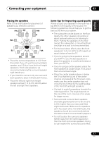 17
17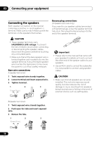 18
18 19
19