Pioneer VSX-24TX Owner's Manual - Page 8
Connecting Your Equipment - remote
 |
View all Pioneer VSX-24TX manuals
Add to My Manuals
Save this manual to your list of manuals |
Page 8 highlights
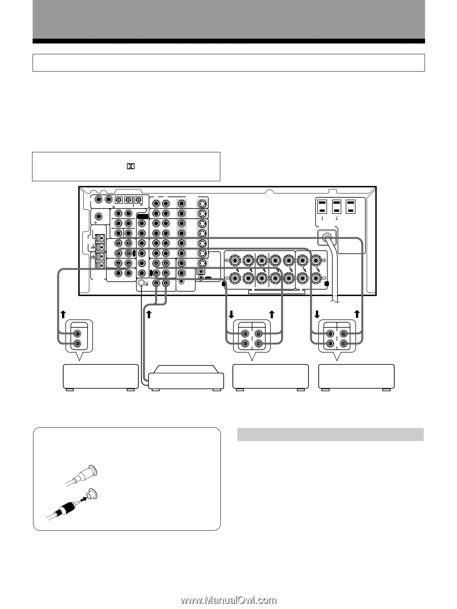
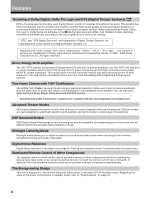
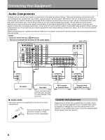
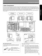
Connecting Your Equipment Audio Components To begin set up connect your audio components to the jacks as shown below. These are all analog connections and your analog audio components (turntable, cassette deck) use these jacks. Remember that for components you want to record with you need to hook up four plugs (a set of stereo ins and a set of stereo outs), but for components that only play (like a turntable) you only need to hook up one set of stereo plugs (two plugs). To use DTS surround sound features you must hook up your digital components to the digital inputs but it is also a good idea to hook up your digital components to analog audio jacks. If you want to record to/from digital components (like an MD) to/from analog components you must hook up your digital equipment with these analog connections. See p.10,11 for more on digital connections. When connecting your equipment always make sure the power is turned off and the power cord is disconnected from the wall outlet. NOTE : • Only the VSX-27TX has a RF IN jack. • The arrows indicate the direction of the audio signal. VSX-27TX R DIGITAL 1 2 3 4 PCM/ /DTS PCM/ /DTS IN OUT PREOUT S S L R EXTERNAL DECODER IN RF IN F L FM UNBAL 75Ω C F F R L S F W R FM ANTENNA TAPE2 MONITOR P L S A L Y R E C S R CD AM LOOP ANTENNA MULTIROOM & SOURCE R I N O U T L P C L A Y S W R E C L DVD /LD IN TV/ SAT IN IN VCR1 OUT VIDEO S2 IN S2 IN S2 IN S2 OUT IN S2 IN VCR2 OUT S2 OUT MD/ TAPE1 VIDEO OUT VIDEO OUT IN PHONO REMOTE IN MULTI-ROOM & SOURCE SWITCHED UNSWITCHED TOTAL 100W(0.8A)MAX 100W(0.8A)MAX AC OUTLETS AC 120V 60Hz TO MONITOR TV S2 OUT FR FL C SR SL R L IN CONTROL OUT A FRONT SPEAKERS CENTER SPEAKERS SURROUND SPEAKERS FRONT B SPEAKERS SEE INSTRUCTION MANUAL SE REPORTER AU MOODE D'EMPLOI OUTPUT L R REC PLAY L R REC PLAY L R CD player Turntable If your turntable has a ground wire, connect it to the SIGNAL GND terminal. 7 Audio cords Use audio cords (not supplied) to connect the audio components. L Connect red plugs to R (right) and white plugs to L (left). R Be sure to insert completely. MD recorder or Cassette deck Cassette deck (with REC monitor) Cassette deck placement Depending on where the cassette deck is placed, noise may occur during playback of your cassette deck which is caused by leakage flux from the transformer in the receiver. If you experience noise, move the cassette deck farther away from the receiver. 8
-
 1
1 -
2
-
 3
3 -
 4
4 -
 5
5 -
 6
6 -
 7
7 -
 8
8 -
 9
9 -
 10
10 -
 11
11 -
 12
12 -
 13
13 -
14
-
15
-
16
-
17
-
18
-
19
-
20
-
21
-
22
-
23
-
24
-
25
-
26
-
27
-
28
-
29
-
30
-
31
-
32
-
33
-
34
-
35
-
36
-
37
-
38
-
39
-
40
-
41
-
42
-
43
-
44
-
45
-
46
-
47
-
48
-
49
-
50
-
51
-
52
-
53
-
54
-
55
-
56
-
57
-
58
-
59
-
60
-
61
-
62
-
63
-
64
-
65
-
66
-
67
-
68
-
69
-
70
-
71
-
72
-
73
-
74
-
75
-
76
-
77
-
78
-
79
-
80
 |
 |