Pioneer VSX-52TX Service Manual - Page 134
Pin Name, Pin Function, Active
 |
View all Pioneer VSX-52TX manuals
Add to My Manuals
Save this manual to your list of manuals |
Page 134 highlights
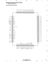
1 2 3 No. Pin Name 46 PIINT A 47 RESET 48 MODO 49 MODC 50 MODB 51 MODA 52 VDDCO 53 GNDCO 54 MUTE 55 PE10 56 PE9 B 57 PE8 58 SDI1_1 59 SDI0_1 60 FST_1 61 PE1 62 SCKT_1 63 PE0 64 VDDIO 65 GNDIO 66 PE5 67 PE2 C 68 GNDCO 69 PD1 70 PD0 71 VDDCO 72 PC2 73 HCKT 74 GNDIO 75 VDDIO 76 SCKR 77 SCKT 78 FSR D 79 FST 80 SDIO I/O Pin Function I PLL initial pin I Reset I Mode select D I Mode select C I Mode select B I Mode select A − Core power supply (1.25V) − Core GND O DSP MUTE output O General-purpose port O General-purpose port O General-purpose port I Digital audio data (Center/Subwoofer) I Digital audio data (Ancillary data) I Digital audio LR clock I General-purpose port: External serial ROM data input I Digital audio bit clock O General-purpose port: Exterenal serial ROM chip select − Interface power supply (3.3V) − Interface GND O General-purpose port: Exterenal serial ROM clock O General-purpose port: Exterenal serial ROM data output − Core GND O General-purpose port: DSP master/slave switch or 96DTS O General-purpose port: BUSY − Core power supply (1.25V) O General-purpose port I Digital audio master clock − Interface GND − Interface power supply (3.3V) I Digital audio Bit clock I/O Digital audio Bit clock I Digital audio Bit clock I/O Digital audio Bit clock I Digital audio data (Surround L/R) E 4 Active L L L H H F 134 VSX-52TX 1 2 3 4
-
 1
1 -
2
-
3
-
4
-
5
-
6
-
7
-
8
-
9
-
10
-
11
-
12
-
13
-
14
-
15
-
16
-
17
-
18
-
19
-
20
-
21
-
22
-
23
-
24
-
25
-
26
-
27
-
28
-
29
-
30
-
31
-
32
-
33
-
34
-
35
-
36
-
37
-
38
-
39
-
40
-
41
-
42
-
43
-
44
-
45
-
46
-
47
-
48
-
49
-
50
-
51
-
52
-
53
-
54
-
55
-
56
-
57
-
58
-
59
-
60
-
61
-
62
-
63
-
64
-
65
-
66
-
67
-
68
-
69
-
70
-
71
-
72
-
73
-
74
-
75
-
76
-
77
-
78
-
79
-
80
-
81
-
82
-
83
-
84
-
85
-
86
-
87
-
88
-
89
-
90
-
91
-
92
-
93
-
94
-
95
-
96
-
97
-
98
-
99
-
100
-
101
-
102
-
103
-
104
-
105
-
106
-
107
-
108
-
109
-
110
-
111
-
112
-
113
-
114
-
115
-
116
-
117
-
118
-
119
-
120
-
121
-
122
-
123
-
124
-
125
-
126
-
127
-
128
-
 129
129 -
 130
130 -
 131
131 -
 132
132 -
 133
133 -
 134
134 -
 135
135 -
 136
136 -
 137
137 -
 138
138 -
 139
139 -
140
-
141
-
142
-
143
-
144
-
145
-
146
-
147
-
148
-
149
 |
 |
