Pioneer VSX-9100TX Operating Instructions - Page 18
Video deck, TV monitor, TV tuner, DVD or LD player
 |
View all Pioneer VSX-9100TX manuals
Add to My Manuals
Save this manual to your list of manuals |
Page 18 highlights
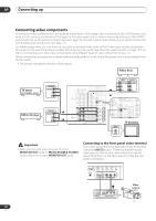
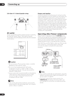
03 Connecting up Connecting video components Connect your video components to the jacks as shown below. With digital video components (like a DVD player), you must use the connections shown on this page for the video signal, but in order to hear a digital source (like a DVD) you should hook up the audio to a digital input (see page 16). It is also a good idea to hook up your digital components with analog audio connections (see page 17). For better quality video, you can hook up using the component video jacks or the S-video jacks (quality descends in this order) on the rear of the receiver instead of the regular video jacks. See About the video converter on page 15 if you plan on connecting your other video components using different types of video cables than for your TV. When connecting your equipment, always make sure the power is turned off and the power cord is disconnected from the AC outlet. • The arrows indicate the direction of the signal. Video deck TV tuner (or Satellite tuner) OUTPUT VIDEO L R DVD or LD player OUTPUT VIDEO L R INPUT OUTPUT VIDEO VIDEO DIGITAL AM LOOP L L R R IN 2 IN 1 (CD-R/ TAPE/MD) (TV/SAT) CD IN ASSIGNABLE 14 PLAY IN CD-R/ TAPE/MD OUT R OUT SUBW. PRE OUT CENTER OUT REC VIDEO1 IN PLAY IN DVR / VCR OUT IN 3 (DVD/ LD) REC TV/ SAT IN IN 4 (CD) DVD/ LD IN R DIGITAL FRONT R L SURROUND R L SUR- ROUND BACK L R (Single) SUBW. R CENTER FRONT L R L AUDIO MULTI CH IN SURROUND L ANTENNA CONTROL MULTI-ROOM & SOURCE MONITOR OUT PR OUT 12V TRIGGER (DC OUT12V/ 100mA MAIXN) OUT CONTROL MONITOR OUT VIDEO1 IN IN DVR / VCR OUT PB Y L MULTI-ROOM & SOURCE PRE MULTIROOM & PB SUBW. PR IN 1 OUT SOURCE CEN- IN TER I R OUT FRONRTS - 232C MONITOR SPEAOKUETRS A R FRONT MONITOR OUT PR L CENTER Y L Y TV/ SAT IN DVD/ LD IN VIDEO S - VIDEO VIDEO SURROUND PB L IN 2 SUR- ROUND PR ASSIGNABLE 12 COMPONENT VIDEO VIDEO1 IN PB IN TV (monitor) R SU INPUT VIDEO Important • Make sure you don't connect your TV to the MONITOR OUT jacks for MULTI-ROOM & SOURCE located above the proper MONITOR OUT jacks. Connecting to the front panel video terminal Front video connections are accessed via the front panel using the VIDEO2 button. There are standard audio/ video jacks as well as an S-video jack and an optical input. Hook them up the same way you made the rear panel connections. TONE ACOUSTIC DIALOG MULTI CH EQ ENHANCEMENT IN MULTI JOG SIGNAL SELECT EXTENDED MODE SPEAKERS MCACC SETUP MIC VIDEO2 INPUT DIGITAL IN S-VIDEO VIDEO L AUDIO R DIGITAL OUT V L R VIDEO OUTPUT Video camera (etc.) 18 En
-
 1
1 -
2
-
3
-
4
-
5
-
6
-
7
-
8
-
9
-
10
-
11
-
12
-
 13
13 -
 14
14 -
 15
15 -
 16
16 -
 17
17 -
 18
18 -
 19
19 -
 20
20 -
 21
21 -
 22
22 -
 23
23 -
24
-
25
-
26
-
27
-
28
-
29
-
30
-
31
-
32
-
33
-
34
-
35
-
36
-
37
-
38
-
39
-
40
-
41
-
42
-
43
-
44
-
45
-
46
-
47
-
48
-
49
-
50
-
51
-
52
-
53
-
54
-
55
-
56
-
57
-
58
-
59
-
60
-
61
-
62
-
63
-
64
-
65
-
66
-
67
-
68
-
69
-
70
-
71
-
72
-
73
-
74
-
75
-
76
-
77
-
78
-
79
 |
 |
