Pioneer VSX-9100TX Operating Instructions - Page 20
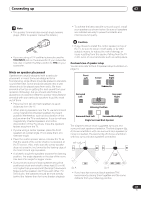
Single, Twist exposed wire strands together., Loosen speaker terminal and insert exposed, wire.,
 |
View all Pioneer VSX-9100TX manuals
Add to My Manuals
Save this manual to your list of manuals |
Page 20 highlights
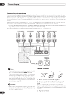
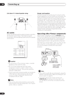
03 Connecting up Connecting the speakers A complete setup of eight speakers (including the subwoofer) is shown below, but everyone's home setup will vary. Simply connect the speakers you have in the manner shown below. The receiver will work with just two stereo speakers (the front speakers in the diagram) but using at least three speakers is recommended, and a complete setup is best for surround sound. If you're not using a subwoofer, change the front speaker setting (see Speaker Setting on page 44) to large. Make sure you connect the speaker on the right to the right terminal and the speaker on the left to the left terminal. Also make sure the positive and negative (+/-) terminals on the receiver match those on the speakers. • You can use speakers with a nominal impedance between 6-16Ω (please see Switching the speaker impedance on page 74 if you plan to use speakers with an impedance of less than 8Ω). Be sure to complete all connections before connecting this unit to the AC power source. Front speakers L R Center speaker C Surround speakers Surround back speakers LS RS SBL SBR DIGITAL AM LOOP MONITOR OUT IN 2 IN 1 (CD-R/ TAPE/MD) (TV/SAT) CD IN ASSIGNABLE 14 PLAY IN CD-R/ TAPE/MD OUT R OUT SUBW. L PRE OUT CENTER OUT REC VIDEO1 IN LAY PLAY IN DVR / VCR OUT IN 3 (DVD/ LD) REC TV/ SAT IN IN 4 (CD) DVD/ LD IN R DIGITAL FRONT R L SURROUND R L SUR- ROUND BACK L R (Single) SUBW. CENTER FRONT R L R R L AUDIO MULTI CH IN SURROUND L D-R/ APE/MD SUBW. ANTENNA IN OUT CONTROL MULTI-ROOM & SOURCE MONITOR OUT MONITOR OUT VIDEO1 IN IN DVR / VCR OUT TV/ SAT IN L DVD/ M LD PREIN OUT VIDEO S - VIDEO VIDEO CEN- TER Y 12V PB TRIGGER (DC OUT12V/ 100mA MAX) PR Y PB IN 1 PR MULTIROOM & SOURCE IN IR OUT Y PB IN 2 PR ASSIGNABLE 12 COMPONENT VIDEO OUT REC DEO1 LAY VR / CR OUT FRONT R L SURROUND R L SURROUND BACK L R (Single) CEN- SPEAKERS A R FRONT L CENTER R SURROUND L INPUT AC OUTLET AC 120 V 60Hz SWITCHED 100W (0 . 8A) MAX SURROUND BACK / B R SELECTABLE L (Single) SELECTABLE Powered subwoofer SW Note Speaker terminals • If you only have one surround back speaker, hook it up to the surround back left (Single) terminal. • If you are planning on bi-amping your front speakers, or setting up a separate speaker system in another room, read through Surround back speaker setting on page 38 and make sure to connect your speakers as necessary (these connections are explained in Other connections on page 56). Caution • Make sure no bare speaker wire is touching the back panel when the unit is switched on. The power may cut off as a safety measure. 1 2 3 3/8 in. (10mm) 1 Twist exposed wire strands together. 2 Loosen speaker terminal and insert exposed wire. Make sure that all the bare speaker wire is twisted together and inserted fully into the speaker terminal. Use good quality speaker wire to connect the speakers to the receiver. 3 Tighten terminal. 20 En
-
 1
1 -
2
-
3
-
4
-
5
-
6
-
7
-
8
-
9
-
10
-
11
-
12
-
13
-
14
-
 15
15 -
 16
16 -
 17
17 -
 18
18 -
 19
19 -
 20
20 -
 21
21 -
 22
22 -
 23
23 -
 24
24 -
 25
25 -
26
-
27
-
28
-
29
-
30
-
31
-
32
-
33
-
34
-
35
-
36
-
37
-
38
-
39
-
40
-
41
-
42
-
43
-
44
-
45
-
46
-
47
-
48
-
49
-
50
-
51
-
52
-
53
-
54
-
55
-
56
-
57
-
58
-
59
-
60
-
61
-
62
-
63
-
64
-
65
-
66
-
67
-
68
-
69
-
70
-
71
-
72
-
73
-
74
-
75
-
76
-
77
-
78
-
79
 |
 |
