Pioneer VSX-919AH-K Owner's Manual - Page 30
Connecting your equipment, Connecting AM/FM antennas
 |
UPC - 012562954691
View all Pioneer VSX-919AH-K manuals
Add to My Manuals
Save this manual to your list of manuals |
Page 30 highlights
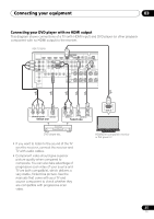
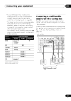
03 Connecting your equipment Connecting AM/FM antennas Connect the AM loop antenna and the FM wire antenna as shown below. To improve reception and sound quality, connect external antennas (see Connecting external antennas below). Connecting external antennas To improve FM reception connect an external FM antenna to the FM UNBAL 75 Ω. 1 2 75 Ω coaxial cable 5 fig. a AM LOOP FM UNBAL 75 ANTENNA fig. b 3 4 fig. c 1 Pull off the protective shields of both AM antenna wires. 2 Push open the tabs, then insert one wire fully into each terminal, then release the tabs to secure the AM antenna wires. 3 Fix the AM loop antenna to the attached stand. To fix the stand to the antenna, bend in the direction indicated by the arrow (fig. a) then clip the loop onto the stand (fig. b). • If you plan to mount the AM antenna to a wall or other surface, secure the stand with screws (fig. c) before clipping the loop to the stand. Make sure the reception is clear. 4 Place the AM antenna on a flat surface and in a direction giving the best reception. 5 Connect the FM wire antenna in the same way as the AM loop antenna. For best results, extend the FM antenna fully and fix to a wall or door frame. Don't drape loosely or leave coiled up. AM LOOP FM UNBAL 75 ANTENNA To improve AM reception, connect a 5 m to 6 m (16 ft. to 20 ft.) length of vinyl-coated wire to the AM LOOP terminals without disconnecting the supplied AM loop antenna. For the best possible reception, suspend horizontally outdoors. Outdoor antenna AM LOOP FM UNBAL 75 ANTENNA Indoor antenna (vinyl-coated wire) 5 m to 6 m (16 ft. to 20 ft.) 30 En
-
 1
1 -
2
-
3
-
4
-
5
-
6
-
7
-
8
-
9
-
10
-
11
-
12
-
13
-
14
-
15
-
16
-
17
-
18
-
19
-
20
-
21
-
22
-
23
-
24
-
 25
25 -
 26
26 -
 27
27 -
 28
28 -
 29
29 -
 30
30 -
 31
31 -
 32
32 -
 33
33 -
 34
34 -
 35
35 -
36
-
37
-
38
-
39
-
40
-
41
-
42
-
43
-
44
-
45
-
46
-
47
-
48
-
49
-
50
-
51
-
52
-
53
-
54
-
55
-
56
-
57
-
58
-
59
-
60
-
61
-
62
-
63
-
64
-
65
-
66
-
67
-
68
-
69
-
70
-
71
-
72
-
73
-
74
-
75
-
76
-
77
-
78
-
79
-
80
-
81
-
82
-
83
-
84
-
85
-
86
-
87
-
88
-
89
-
90
-
91
-
92
-
93
-
94
-
95
-
96
-
97
-
98
-
99
-
100
-
101
-
102
-
103
-
104
-
105
-
106
-
107
-
108
-
109
-
110
-
111
-
112
-
113
-
114
-
115
-
116
-
117
-
118
-
119
-
120
-
121
-
122
-
123
-
124
-
125
-
126
-
127
-
128
 |
 |
