Pioneer VSX-LX505 ELITE 9.2 Channel AV Receiver Instruction Manual English - Page 11
Part Names, Front Panel
 |
View all Pioneer VSX-LX505 ELITE 9.2 Channel AV Receiver manuals
Add to My Manuals
Save this manual to your list of manuals |
Page 11 highlights
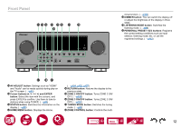
Part Names Front Panel A B C DE F G H I JK A INPUT SELECTOR dial: Switch the input to be played. B FL OFF indicator: Lights up when the display is turned off by repeatedly pressing the DIMMER button on the remote controller. C Display ( →p13) D NETWORK indicator: This lights when "NET" is selected with the input selector and the unit is connected to the network. Lights up when any of the following functions is working or LM I enabled in standby state of this unit. When this indicator is lighting, the power consumption in standby state increases, however, the increase in power consumption is minimized by entering the HYBRID STANDBY mode where only the essential circuits operate. It does not light when ZONE 2/ZONE 3 is on, however. -- HDMI CEC ( →p142) -- HDMI Standby Through ( →p142) -- USB Power Out at Standby ( →p144) -- Network Standby ( →p145) -- Bluetooth Wakeup ( →p145) E Remote control sensor: Receives signals from the remote controller. • The signal range of the remote controller is within about 16´/5 m, at an angle of 20° on the perpendicular axis and 30° to either side. F Advanced MCACC indicator: This lights when you have enabled the speaker calibration made with MCACC. ( →p153, p170) G MASTER VOLUME H STANDBY/ON button: When the power is turned on, the periphery of the button lights up. It also lights up when ZONE 2/ZONE 3 is turned on. I Front flap J PHONES jack: Headphones with a standard plug (ø1/4" / 6.3 mm) are connected. K SETUP MIC jack: Connect the supplied speaker setup microphone. ( →p153, p170) L USB port: A USB storage device is connected so that music files stored in it can be played. Supply of power to USB devices while in the standby mode is not supported. ( →p114) M AUX INPUT HDMI jack: Connect a video camera, etc. using an HDMI cable. ( →p69) 11
-
 1
1 -
2
-
3
-
4
-
5
-
 6
6 -
 7
7 -
 8
8 -
 9
9 -
 10
10 -
 11
11 -
 12
12 -
 13
13 -
 14
14 -
 15
15 -
 16
16 -
17
-
18
-
19
-
20
-
21
-
22
-
23
-
24
-
25
-
26
-
27
-
28
-
29
-
30
-
31
-
32
-
33
-
34
-
35
-
36
-
37
-
38
-
39
-
40
-
41
-
42
-
43
-
44
-
45
-
46
-
47
-
48
-
49
-
50
-
51
-
52
-
53
-
54
-
55
-
56
-
57
-
58
-
59
-
60
-
61
-
62
-
63
-
64
-
65
-
66
-
67
-
68
-
69
-
70
-
71
-
72
-
73
-
74
-
75
-
76
-
77
-
78
-
79
-
80
-
81
-
82
-
83
-
84
-
85
-
86
-
87
-
88
-
89
-
90
-
91
-
92
-
93
-
94
-
95
-
96
-
97
-
98
-
99
-
100
-
101
-
102
-
103
-
104
-
105
-
106
-
107
-
108
-
109
-
110
-
111
-
112
-
113
-
114
-
115
-
116
-
117
-
118
-
119
-
120
-
121
-
122
-
123
-
124
-
125
-
126
-
127
-
128
-
129
-
130
-
131
-
132
-
133
-
134
-
135
-
136
-
137
-
138
-
139
-
140
-
141
-
142
-
143
-
144
-
145
-
146
-
147
-
148
-
149
-
150
-
151
-
152
-
153
-
154
-
155
-
156
-
157
-
158
-
159
-
160
-
161
-
162
-
163
-
164
-
165
-
166
-
167
-
168
-
169
-
170
-
171
-
172
-
173
-
174
-
175
-
176
-
177
-
178
-
179
-
180
-
181
-
182
-
183
-
184
-
185
-
186
-
187
-
188
-
189
-
190
-
191
-
192
-
193
-
194
-
195
-
196
-
197
-
198
-
199
-
200
-
201
-
202
-
203
-
204
-
205
-
206
-
207
-
208
-
209
-
210
-
211
-
212
 |
 |
