Poulan 1600 User Manual - Page 7
reinstall.
 |
View all Poulan 1600 manuals
Add to My Manuals
Save this manual to your list of manuals |
Page 7 highlights
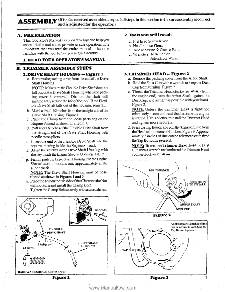
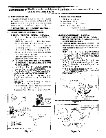
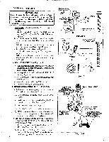
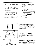
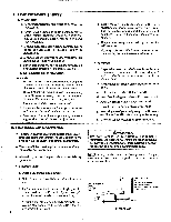
ASSEMBLY (If tool is received assembled, repeat all steps in this section to be sure assembly is correct and is adjusted for the operator.) A. PREPARATION This Operator's Manual has been developed to help you assemble the tool and to provide its safe operation. It is important that you read the entire manual to become familiar with the tool before you begin assembly. 1. READ YOUR OPERATOR'S MANUAL B. TRIMMER ASSEMBLY STEPS 1 .DRIVE SHAFT HOUSING Figure 1 a. Remove the packing cover from theend ofthe Drive Shaft Housing. NOTE: Make sure the Flexible Drive Shaft does not fall out of the Drive Shaft Housing when the packing cover is removed. Dirt on the shaft will significantly reduce the life of the tool. If the Flexible Drive Shaft falls out of the housing, reinstall. b. Mark a line 1-1/2 inches from the straight end of the Drive Shaft Housing. Figure 1. c. Place the Clamp from the loose parts bag on the Engine Shroud as shown in Figure 1. d. Pull about 6 inches of the Flexible Drive Shaft from the straight end of the Drive Shaft Housing with needle-nose pliers. e. Insert the end of the Flexible Drive Shaft into the square opening inside the Engine Shroud. f. Align the keyway in the Drive Shaft Housing with the key inside the Engine Shroud Opening. Figure 1. g. Firmly push the Drive Shaft Housing into the Engine Shroud until it bottoms out, approximately at the 1-1/2 " mark. NOTE: The Drive Shaft Housing must be positioned as shown in Figures 1 and 5. h. Placethe Nut onthetab sideof theClampsotheNut will not turn and install the Clamp Bolt. i. Tighten the Clamp Bolt securely with a screwdriver. 2.Tools you will need: a. Flat head Screwdriver b. Needle-nose Pliers c. Tape Measure & Grease Pencil d. Wrenches: 1-1/4 inch or Adjustable Wrench 2.TRIMMER HEAD - Figure 2 a. Remove the packing cover from the Arbor Shaft. b. Hold the Dust Cup with a wrench to keep the Dust Cup from turning. Figure 2. c. Thread the Trimmer Head clockwise u•-k (from the engine end) onto the Arbor Shaft, against the Dust Cup, and as tight as possible with your hand. Figure 2. NOTE: Unless the Trimmer Head is tightened adequately, it can unthread the first time theengine is started. If this occurs, reinstall the Trimmer Head and tighten more securely. d. Press the Tap Button and pull the Trimmer Line from the Head a minimum of 4 inches. Figure 3. Approximately 2 inches of line can be advanced each time the Tap Button is pressed. NOTE: To remove Trimmer Head, hold the Dust Cup with a wrench and unthread the Trimmer Head counterclockwise I-1/4 " WRENCH DIRECTION TO INSTALL 0 NUT • ti ro FLEXIBLE DRIVE SHAFT MARK 1'h " SCREW KEYWAY KEY DRIVE SHAFT HOUSING Figure 2 ARBOR SHAFT DUST CUP Approximately 2 inches of line can be advanced each time the Tap Button is pressed. TAP BUTTON HARDWARE SHOWN ACTUAL SIZE Figure 1 Figure 3 7
-
 1
1 -
 2
2 -
 3
3 -
 4
4 -
 5
5 -
 6
6 -
 7
7 -
 8
8 -
 9
9 -
 10
10 -
 11
11 -
 12
12 -
13
-
14
-
15
-
16
-
17
-
18
-
19
-
20
-
21
-
22
-
23
-
24
 |
 |