Poulan 1992-05 User Manual - Page 7
Assembly, Notes
 |
View all Poulan 1992-05 manuals
Add to My Manuals
Save this manual to your list of manuals |
Page 7 highlights
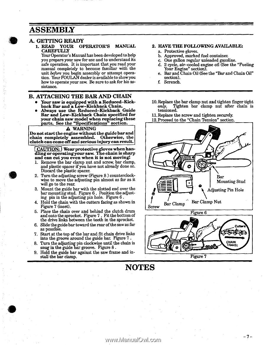
ASSEMBLY A. GETTING READY 1. READ YOUR OPERATOR'S MANUAL CAREFULLY Your Operator's Manual has been developed to help you prepare your saw for use and to understand its safe operation. It is important that you read your manual completely to become familiar with the unit before you begin assembly or attempt operation. Your POULAN dealer is available to showyou how to operate your saw. Be sure to ask for his as- sistance. 2. HAVE THE FOLLOWING AVAILABLE: a. Protective gloves. b. Approved, marked fuel container. c. One gallon regular unleaded gasoline. d. 2 cycle, air-cooled engine oil (See the "Fueling Your Engine" section). e. Bar and Chain Oil (See the "Bar and Chain Oil" section). f Scrench. B. ATTACHING THE BAR AND CHAIN • Your saw is equipped with a Reduced-Kickback Bar and a Low-Kickback Chain. • Always use the Reduced-Kickback Guide Bar and Low-Kickback Chain specified for your chain saw model when replacingthese parts. See the "Specifications section. A WARNING Do not start the engine without the guidebarand chain completely assembled. Otherwise, the clutch can come off and serious injury can result. CAUTION: Wear protective gloves when handlingor operatingyour saw. The chain is sharp and can cut you even when it is not movin,gt 1. Remove the bar clamp nut and screw, bar clamp, and plastic spacer if you have not already done so. Discard the plastic spacer. 2. Turn the adjusting screw (Figure 8 ) counterclockwise to move the adjusting pin almost as far as it will go to the rem: 3. Mount the guide bar with the slotted end over the bar mounting stud. Figure 6 . Position the adjusting pin in the adjusting pm hole. Figure 6 . 4. Hold the chain with the cutters facing as shown in Figure 7 (inset). 5. Place the chain over and behind the clutch drum and onto the sprocket. Figure 7 . Fit the bottom of the drive links between the teeth in the sprocket. 6. Slide the guide bar toward the rear of the sawas far as possible. 7. Start at the top of the bar and fit chain drive links into the groove around the guide bar. Figure 7 . 8. Turn the adjusting pin clockwise until the chain is snug in the guide bar groove. Figure 8 . 9. Hold the guide bar against the saw frame and install the bar clamp. 10. Replace the bar clamp nut and tighten finger tight only. Tighten bar clamp nut after chain is tensioned. 11. Replace the screw and tighten securely 12. Proceed to the "Chain Tension" section. 0 Bar Mounting Stud === \Adjusting Pin Hole Bar Clamp Bar Clamp Nut Screw Figure 6 Gutters 4:0 Figure 7 CHAIN TRAVEL NOTES -7-
-
 1
1 -
 2
2 -
 3
3 -
 4
4 -
 5
5 -
 6
6 -
 7
7 -
 8
8 -
 9
9 -
 10
10 -
 11
11 -
 12
12 -
13
-
14
-
15
-
16
-
17
-
18
-
19
-
20
-
21
-
22
-
23
-
24
 |
 |