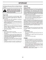
Poulan PBA195H42LT User Manual - Page 21
Transaxle, Motion Control Lever, Neutral Adjustment See Fig. 23, To Check And Adjust Brake, See Fig
 |
View all Poulan PBA195H42LT manuals
Add to My Manuals
Save this manual to your list of manuals |
Page 21 highlights
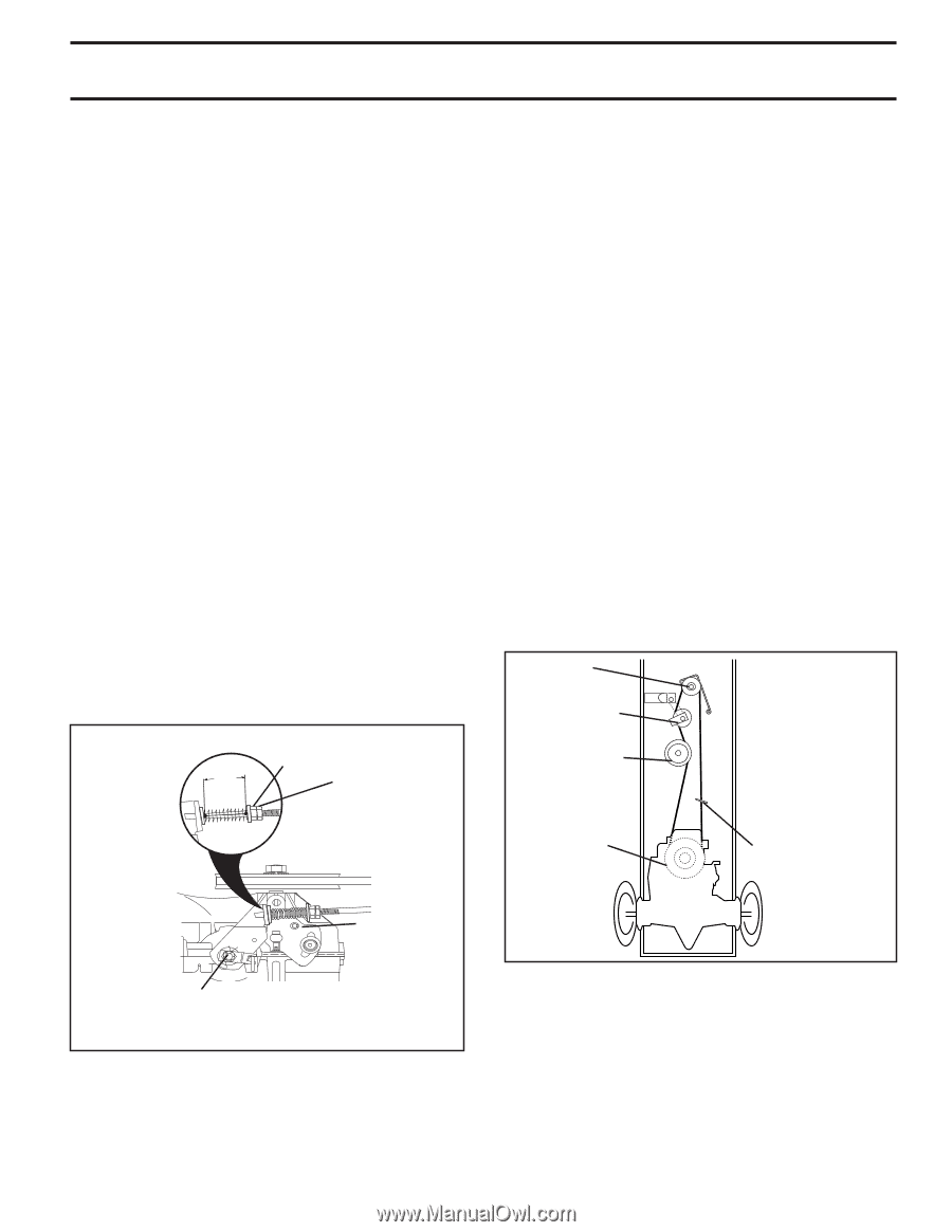
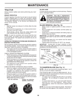
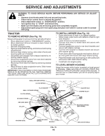
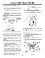
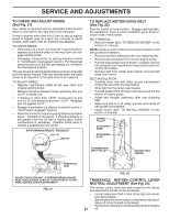
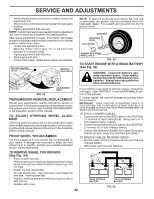
SERVICE AND ADJUSTMENTS TO CHECK AND ADJUST BRAKE (See Fig. 21) Your tractor is equipped with an adjustable brake system which is mounted on the right side of the transaxle. If tractor requires more than five (5) feet to stop at highest speed in highest gear on a level, dry concrete or paved surface, then brake must be checked and adjusted. TO CHECK BRAKE • Park tractor on a level, dry concrete or paved surface, depress clutch/brake pedal all the way down and engage parking brake. • Disengage transmission by placing freewhel control in "transmission disengaged" position. Pull freewheel control out and into the slot and release so it is held in the disengaged position. The rear wheels must lock and skid when you try to manually push the tractor forward. If the rear wheels rotate, the brake needs to be adjusted or the pads need to be replaced. TO ADJUST BRAKE • Depress clutch/brake pedal all the way down and engage parking brake. • Measure distance between brake operating arm and nut "A" on brake rod. • If distance is other than 1-9/16", loosen jam nut and turn nut "A" until distance becomes 1-9/16". Retighten jam nut against nut "A". • Engage transmission by placing freewheel control in "transmission engaged" position. • Road test tractor for proper stopping distance as stated above. Readjust if necessary. If stopping distance is still greater than five (5) feet in highest gear, further maintenance is necessary. Replace brake pads or contact a qualified service center. WITH PARKING BRAKE "ENGAGED" 1-9/16" NUT "A" JAM NUT TO REPLACE MOTION DRIVE BELT (See Fig. 22) Park the tractor on level surface. Engage parking brake. For assistance, there is a belt installation guide decal on bottom side of left footrest. BELT REMOVAL • Remove mower (See "TO REMOVE MOWER" in this section of manual). NOTE: Observe entire motion drive belt and position of all belt guides and keepers. • Remove belt from stationary idler and clutching idler. • Remove belt downward from around engine pulley. • Pull belt slack toward rear of tractor. Carefully remove belt upwards from transmission input pulley and over cooling fan blades. • Remove belt from center span keeper and pull belt away from tractor. BELT INSTALLATION • Carefully work new belt down around transmission cooling fan and onto the input pulley. • Slide belt into the center span keeper. • Pull belt toward front of tractor and roll around the top groove of engine pulley. • Install belt through stationary idler and clutching idler. • Make sure belt is in all pulley grooves and inside all belt guides and keepers. • Install mower (See "TO INSTALL MOWER" in this section of manual). ENGINE PULLEY CLUTCHING IDLER STATIONARY IDLER TRANSMISSION INPUT PULLEY CENTER SPAN KEEPER OPERATING ARM 01513 DO NOT TOUCH THIS NUT. IF FURTHER BRAKE ADJUSTMENT IS NECESSARY CONTACT YOUR NEAREST AUTHORIZED SERVICE CENTER/DEPARTMENT FIG. 21 FIG. 22 TRANSAXLE MOTION CONTROL LEVER NEUTRAL ADJUSTMENT (See Fig. 23) The motion control lever has been preset at the factory and adjustment should not be necessary. • • • 21 Loosen adjustment bolt in front of the right rear wheel, and lightly tighten. Start engine and move motion control lever until tractor does not move forward or backward. Hold motion control lever in that position and turn engine off.
-
 1
1 -
2
-
3
-
4
-
5
-
6
-
7
-
8
-
9
-
10
-
11
-
12
-
13
-
14
-
15
-
 16
16 -
 17
17 -
 18
18 -
 19
19 -
 20
20 -
 21
21 -
 22
22 -
 23
23 -
 24
24 -
 25
25 -
 26
26 -
27
-
28
-
29
-
30
-
31
-
32
-
33
-
34
-
35
-
36
-
37
-
38
-
39
-
40
-
41
-
42
-
43
-
44
-
45
-
46
-
47
-
48
-
49
-
50
-
51
-
52
-
53
-
54
-
55
-
56
-
57
-
58
-
59
-
60
 |
 |