Poulan PP15H42KA User Manual - Page 3
Assembly
 |
View all Poulan PP15H42KA manuals
Add to My Manuals
Save this manual to your list of manuals |
Page 3 highlights
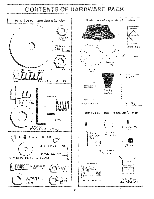
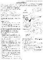
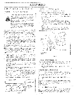
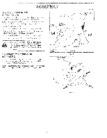
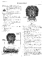
ASSEMBLY ur new tractor has been assembled at the factory with exception of those parts left unassembled for shipping purposes. o ensure safe and proper operation of your tractor all parts and hardware you assemble must be tightened securely. Use ie correct tools as necessary to insure proper tightness. COOLS REQUIRED FOR ASSEMBLY INSERT socket wrench set will make assembly easier. Standard irench sizes are listed. 2) 7/16" wrenches Phillips Screwdriver 1) 1/2" wrench Tire pressure gauge 3/8-24 LOCKNUT q,LARGE FLAT WASHER I -- 1) 9/16" wrench Utility knife Vhen right or left hand is mentioned in this manual, it leans when you are in the operating position (seated iehind the steering wheel). STEERING WHEEL RETAINER CLIPS a ro REMOVE TRACTOR FROM CARTON (TAB TO OUTSIDE) STEERING WHEEL HUB STEERING SLEEVE ADAPTER JNPACK CARTON Remove all accessible loose parts and parts cartons • ) from carton (See page 2). Cut, from top to bottom, along lines on all four corners of carton, and lay panels flat. Check for any additional loose parts or cartons and remove. ADJUSTABLE EXTENSION SHAFT 5/16 HEX BOLT 3EFOREROLLINGTRACTOROFFSKID STEERING SLEEVE kTTACH STEERING WHEEL (See Fig. 1) 'REASSEMBLE SLEEVE TO STEERING WHEEL 5/16 LOCKNUT See Fig. 1 Inset) Install sleeve retainer clips, evenly spaced around steering wheel hub, with formed tabs toward the outside of hub. LOWER STEERING SHAFT ----- . Press or lightly tap the retainer clips fully onto the steering wheel hub. FIG. 1 Press steering sleeve fully onto steering wheel hub and clips. SSEMBLE ADJUSTABLE EXTENSION SHAFT "he steering wheel may be assembled in a high, medium, itlow position. Position is determined by which of the three nounting holes is used in the extension shaft. Slide extension shaft onto lower steering shaft. Align desired mounting holes and install 5/16 hex bolt and locknut. Tighten securely. NISTALL STEERING WHEEL IMPORTANT: CHECK FOR AND REMOVE ANY STAPLES IN SKID THAT MAY PUNCTURE TIRES WHERE TRACTOR IS TO ROLL OFF SKID. TO ROLL TRACTOR OFF SKID • Raise attachment lift lever to its highest position (See Operator's manual). • Release parking brake by depressing clutch/brake pedal(See Operator's manual). • Disengage transmission by placing freewheel control in freewheeling position (See Operator's manual). Position front wheels of the tractor so they are pointing straight forward. Slide steering wheel adapter onto steering shaft extension. • Roll tractor backwards off skid. • Remove banding holding discharge guard up against tractor. Position steering wheel and sleeve assembly so cross bars are horizontal (left to right) and slide onto adapter. Assemble large flat washer and 3/8-24 locknut and tighten securely. Snap steering wheel insert into center of steering wheel. Remove protective plastic from tractor hood and grill. 3
-
 1
1 -
 2
2 -
 3
3 -
 4
4 -
 5
5 -
 6
6 -
 7
7 -
 8
8 -
 9
9 -
10
-
11
-
12
-
13
-
14
-
15
-
16
-
17
-
18
-
19
-
20
-
21
-
22
-
23
-
24
-
25
-
26
-
27
-
28
-
29
-
30
-
31
-
32
-
33
-
34
-
35
-
36
-
37
-
38
-
39
-
40
-
41
-
42
-
43
-
44
-
45
-
46
-
47
-
48
-
49
-
50
-
51
-
52
-
53
-
54
 |
 |
