ProForm 480 E Treadmill English Manual - Page 11
If The Connectors Are Not Con
 |
View all ProForm 480 E Treadmill manuals
Add to My Manuals
Save this manual to your list of manuals |
Page 11 highlights
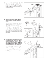
12. Set the Pulse Support (111) on the console assembly. Make sure that no wires are pinched. Tighten two M4 x 20mm Screws (2) into the Pulse Support (111). Tighten six M4 x 19mm Screws (35) into the Pulse Support (111) and console assembly. Start all six Screws before tightening any of them. 12 2 35 35 35 2 111 Console Assembly 13. Have a second person hold the console assembly near the Right Upright (89). Connect the Wire Harness (88) to the console wire. See the inset drawing. The connectors should slide together easily and snap into place. If they do not, turn one connector and try again. IF THE CONNECTORS ARE NOT CONNECTED PROPERLY, THE CONSOLE MAY BE DAMAGED WHEN THE POWER IS TURNED ON. Remove the long tie from the Wire Harness and the tie from the console wire. Then, insert the connectors into the Right Upright (89). Set the console assembly on the Right Upright (89) and the Left Upright (not shown). Make sure that no wires are pinched. 13 88 Console Assembly Console Wire Long Tie Console Wire 89 88 11
-
 1
1 -
2
-
3
-
4
-
5
-
 6
6 -
 7
7 -
 8
8 -
 9
9 -
 10
10 -
 11
11 -
 12
12 -
 13
13 -
 14
14 -
 15
15 -
 16
16 -
17
-
18
-
19
-
20
-
21
-
22
-
23
-
24
-
25
-
26
-
27
-
28
-
29
-
30
-
31
-
32
 |
 |
