ProForm 485 E Elliptical Uk Manual - Page 7
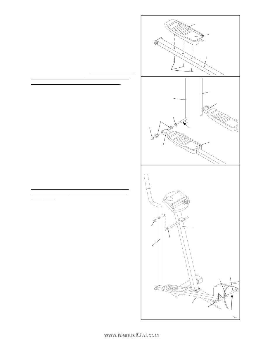
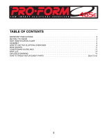
tify the 3/4 Axle Caps 43. Tap a 3/4 Axle Cap onto
 |
View all ProForm 485 E Elliptical manuals
Add to My Manuals
Save this manual to your list of manuals |
Page 7 highlights
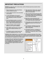
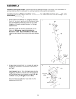
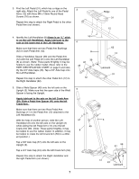
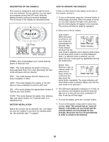
3. Find the Left Pedal (31), which has a ridge on the right side. Attach the Left Pedal to one of the Pedal 3 Arms (12) with three M4 x 19mm Round Head Screws (16) as shown. Repeat this step to attach the Right Pedal to the other Pedal Arm (not shown). 4. Identify the Left Handlebar (8) (there is an "L" sticker on the Left Handlebar). Apply lubricant to the axle on the lower end of the Left Handlebar. Make sure that there are two Pedal Arm Bushings (42) in each Pedal Arm (12). Slide a Handlebar Spacer (39) and the Pedal Arm (12) with the Left Pedal (31) onto the Left Handlebar (8) as shown. (Note: These parts fit tightly; it may be helpful to use the rubber mallet.) Next, refer to the PART IDENTIFICATION CHART on page 5 and identify the 3/4" Axle Caps (43). Tap a 3/4" Axle Cap onto the Left Handlebar. Repeat this step to attach the other Pedal Arm (12) to the Right Handlebar (62). 5. Slide a Weld Spacer (49) onto the left axle on the Upright (3). Make sure that the open side of the Weld Spacer is facing the Upright. Apply lubricant to the axle on the left Crank Arm (59). Slide a Pedal Arm Spacer (41) onto the left Crank Arm. Make sure that there are two Rear Pedal Arm Bushings (11) in the Pedal Arm (12) attached to the Left Handlebar (8). With the help of another person, slide the Left Handlebar (8) onto the left axle on the Upright (3) while sliding the left Pedal Arm (12) onto the left Crank Arm (59). (Note: These parts fit tightly; it may be helpful to use the rubber mallet. In addition, it may be helpful to rotate the left Crank Arm (59) to a different position.) Tap a 5/8" Axle Cap (57) onto the left axle on the Upright (3). Tap a 3/4" Axle Cap (43) onto the left Crank Arm (59). Repeat this step to attach the Right Handlebar and the right Pedal Arm (not shown). 16 4 8 39 42 43 12 5 57 49 8 7 Ridge 31 12 62 12 Lubricant 31 3 59 41 11 12 43 Lubricant
-
 1
1 -
 2
2 -
 3
3 -
 4
4 -
 5
5 -
 6
6 -
 7
7 -
 8
8 -
 9
9 -
 10
10 -
 11
11 -
 12
12 -
13
-
14
-
15
-
16
 |
 |