ProForm 505 Zle Instruction Manual - Page 24
Key No., Description
 |
View all ProForm 505 Zle manuals
Add to My Manuals
Save this manual to your list of manuals |
Page 24 highlights
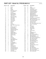
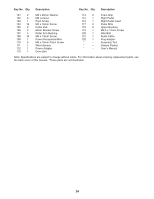
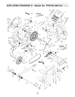
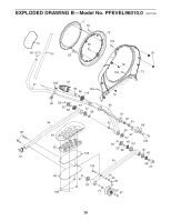
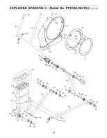
Key No. Qty. Description Key No. Qty. Description 101 2 102 6 103 1 104 16 105 2 106 2 107 4 108 10 109 1 110 4 111 1 112 1 113 1 M8 x 20mm Washer M8 Locknut Pivot Screw M4 x 16mm Screw Pedal Pad Motor Bracket Screw Roller Arm Bushing M6 x 13mm Screw Power Receptacle/Wire M8 x 16mm Patch Screw Wire Harness Power Adapter Drive Belt 114 2 115 1 116 1 117 2 118 2 119 1 120 1 121 1 122 1 * - * - * - Foam Grip Right Pedal Right Pedal Insert Pulse Wire Upper Bushing M3.5 x 12mm Screw Idler Bolt Audio Cable Plug Adapter Assembly Tool Grease Packet Userʼs Manual Note: Specifications are subject to change without notice. For information about ordering replacement parts, see the back cover of this manual. *These parts are not illustrated. 24
-
 1
1 -
2
-
3
-
4
-
5
-
6
-
7
-
8
-
9
-
10
-
11
-
12
-
13
-
14
-
15
-
16
-
17
-
18
-
 19
19 -
 20
20 -
 21
21 -
 22
22 -
 23
23 -
 24
24 -
 25
25 -
 26
26 -
 27
27 -
 28
28
 |
 |

24
101
2
M8 x 20mm Washer
102
6
M8 Locknut
103
1
Pivot Screw
104
16
M4 x 16mm Screw
105
2
Pedal Pad
106
2
Motor Bracket Screw
107
4
Roller Arm Bushing
108
10
M6 x 13mm Screw
109
1
Power Receptacle/Wire
110
4
M8 x 16mm Patch Screw
111
1
Wire Harness
112
1
Power Adapter
113
1
Drive Belt
114
2
Foam Grip
115
1
Right Pedal
116
1
Right Pedal Insert
117
2
Pulse Wire
118
2
Upper Bushing
119
1
M3.5 x 12mm Screw
120
1
Idler Bolt
121
1
Audio Cable
122
1
Plug Adapter
*
–
Assembly Tool
*
–
Grease Packet
*
–
Userʼs Manual
Key No.
Qty.
Description
Key No.
Qty.
Description
Note: Specifications are subject to change without notice. For information about ordering replacement parts, see
the back cover of this manual. *These parts are not illustrated.