ProForm 590hr Treadmill User Manual - Page 8
Press the Latch Knob Sleeve 75 into the Left Upright
 |
View all ProForm 590hr Treadmill manuals
Add to My Manuals
Save this manual to your list of manuals |
Page 8 highlights
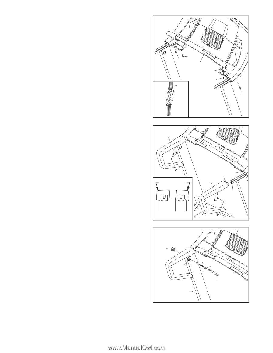
5. Hold the Pulse Bar (125) near the Console Base (85). 5 Connect the Pulse Wire (124) on the Pulse Bar to the in- dicated wire on the Console Base. The connectors should slide together easily and snap into place. If the connectors do not slide together easily and snap into place, turn one connector and try to connect them again. Insert the wires into the hole in the Console Base. Have a second person hold the Pulse Bar (125) firmly on the Console Base (85). Attach the Pulse Bar to the Console Base with two 1 1/4" Screws (92) in the locations shown. Be careful not to damage the Pulse Wire (124) or the wire on the Console Base. Next, tighten two 2" Silver Screws (93) into the Console Base and the Pulse Bar in the locations shown. Note: The correct Screws must be used in the correct locations, or the Pulse Bar may be damaged. 93 92 125 124 93 85 124 92 6. Identify the Left and Right Handrails (68, 81) (see the end views of the Handrails in the inset drawing). The curved edges of the Handrails should be on the outside. Slide the Right Handrail (81) onto the Right Handrail Bracket (113), and press the lip on the front of the Right Handrail under the Console Base (85). (Note: It may be helpful to tip the Right Handrail and to tap it with a rubber mallet to correctly position it.) Tighten three 3/4" Screws (6) into the Right Handrail as shown. Note: It may be necessary to move the lower end of the Right Handrail slightly to align the lower screw hole. Attach the Left Handrail (68) in the same way. See assembly step 1. Tighten the four 1 1/4" Bolts (104). 6 68 6 Curved Edge (81) (68) Lip 85 81 113 6 7. Press the Latch Knob Sleeve (75) into the Left Upright (69). Note: It may be helpful to use a rubber mallet to fully insert the Latch Knob Sleeve. Remove the Latch Knob (70) from the Latch Pin (80). Make sure that the Latch Pin Collar (78) and the Spring (77) are on the Latch Pin. (Note: If there are two Latch Pin Collars, place one on each side of the Spring.) Insert the Latch Pin into the Left Upright (69) and tighten the Latch Knob onto the Latch Pin. 7 70 77 75 78 80 69 8. Make sure that all parts are properly tightened before you use the treadmill. Note: Extra hardware may be included. Keep the included hex keys in a secure place. The large hex key is used to adjust the walking belt (see page 26). To protect the floor or carpet, place a mat under the treadmill. 8
-
 1
1 -
2
-
 3
3 -
 4
4 -
 5
5 -
 6
6 -
 7
7 -
 8
8 -
 9
9 -
 10
10 -
 11
11 -
 12
12 -
 13
13 -
14
-
15
-
16
-
17
-
18
-
19
-
20
-
21
-
22
-
23
-
24
-
25
-
26
-
27
-
28
-
29
-
30
-
31
-
32
-
33
-
34
 |
 |