ProForm 696 Elliptical Uk Manual - Page 20
HOW TO ADJUST THE BELT, there are three sizes of screws in the side, shields-note which size
 |
View all ProForm 696 Elliptical manuals
Add to My Manuals
Save this manual to your list of manuals |
Page 20 highlights
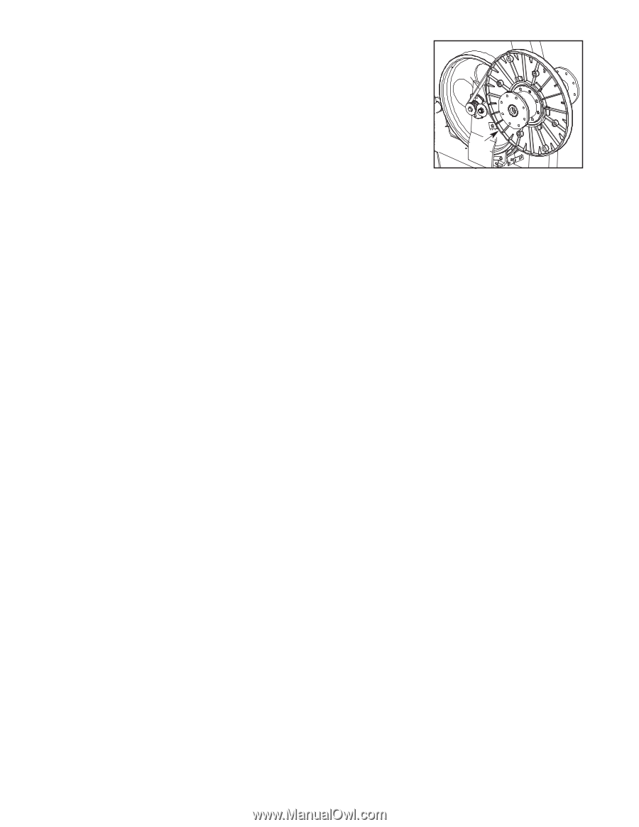
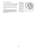
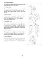
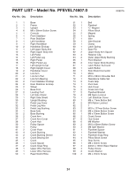
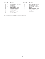
HOW TO ADJUST THE BELT If you can feel the pedals slip while you are pedaling, even when the resistance of the pedals is at the highest setting, the Belt (51) may need to be adjusted. First, see step 11 on page 10 and remove the link arms. Next, see step 4 on page 7 and remove the crank arms. Then, remove all the screws from both side shields; there are three sizes of screws in the side shields-note which size of screw you remove from each hole. Then, gently pry the side shields away from the frame. Next, tighten the M8 x 35mm Screw (96) until the Belt 51 (51) is tight. Then, reattach the side shields, the crank arms, and the link arms. Note: If you have questions as 96 to which screw should be in which hole, see EXPLODED DRAWING B on page 27 and the PART LIST on page 24. 20
-
 1
1 -
2
-
3
-
4
-
5
-
6
-
7
-
8
-
9
-
10
-
11
-
12
-
13
-
14
-
 15
15 -
 16
16 -
 17
17 -
 18
18 -
 19
19 -
 20
20 -
 21
21 -
 22
22 -
 23
23 -
 24
24 -
 25
25 -
26
-
27
-
28
 |
 |