ProForm 8.0 Ex Bike English Manual - Page 10
Attach the Accessory Tray 8 to the Upright 4
 |
View all ProForm 8.0 Ex Bike manuals
Add to My Manuals
Save this manual to your list of manuals |
Page 10 highlights
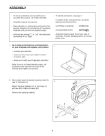
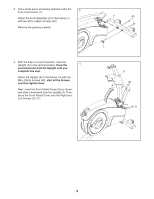
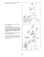
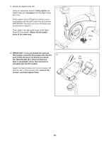
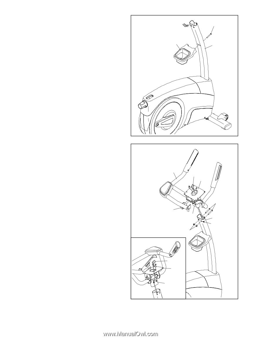
5. Attach the Accessory Tray (8) to the Upright (4) with an M6 x 50mm Screw (89). 5 89 8 4 6. Have a second person hold the Handlebar (5) near the Upright (4). See the inset drawing. Route the Upper Wire (87) through the Pivot Post (78) and the Pivot Bracket (71) as shown. Tip: It may be easier to route the Upper Wire if you adjust the angle of the Pivot Bracket by turning the Console Knob (77). Tip: Avoid pinching the wires. Insert the Pivot Post (78) into the Upright (4). Attach the Pivot Post (78) to the Upright (4) with two M8 x 50mm Bolts (70) and two M8 Locknuts (43); make sure that the Locknuts are in the hexagonal holes. 6 5 87 71 77 Avoid pinching the wires 78 43 70 4 Hexagonal Holes 87 71 78 10
-
 1
1 -
2
-
3
-
4
-
 5
5 -
 6
6 -
 7
7 -
 8
8 -
 9
9 -
 10
10 -
 11
11 -
 12
12 -
 13
13 -
 14
14 -
 15
15 -
16
-
17
-
18
-
19
-
20
-
21
-
22
-
23
-
24
-
25
-
26
-
27
-
28
-
29
-
30
-
31
-
32
 |
 |
10
5
8
4
89
5.
Attach the Accessory Tray (8) to the Upright (4)
with an M6 x 50mm Screw (89).
6
6.
Have a second person hold the Handlebar (5)
near the Upright (4).
See the inset drawing.
Route the Upper Wire
(87) through the Pivot Post (78) and the Pivot
Bracket (71) as shown.
Tip: It may be easier to
route the Upper Wire if you adjust the angle
of the Pivot Bracket by turning the Console
Knob (77).
Tip: Avoid pinching the wires.
Insert the Pivot
Post (78) into the Upright (4).
Attach the Pivot Post (78) to the Upright (4) with
two M8 x 50mm Bolts (70) and two M8 Locknuts
(43); make sure that the Locknuts are in the
hexagonal holes.
4
71
43
70
78
87
87
71
78
5
Hexagonal
Holes
Avoid pinching
the wires
77