ProForm 890e English Manual - Page 12
ProForm 890e Manual
 |
View all ProForm 890e manuals
Add to My Manuals
Save this manual to your list of manuals |
Page 12 highlights
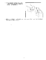
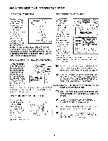
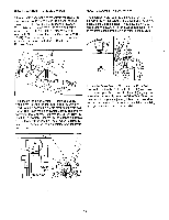
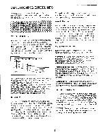
HOW TO ADJUST THE REED SWITCH If the console does not display correct feedback, the reed switch should be adjusted. To adjust the reed switch, the Left Side Shield (24) and the Flywheel Cover (31) must be removed. Using an adjustable wrench, turn the Left Pedal (20) clockwise and remove it. Next, remove the indicated Screws (2, 32, 35, 49). Turn the Left Crank Arm (66) to the position shown and slide off the Left Side Shield and the Flywheel Cover. HOW TO ADJUST THE DRIVE BELT The exercise cycle features a Drive Belt (1) that must be kept properly adjusted. If the Drive Belt slips as you pedal, it should be adjusted. To do this, the left side shield and the flywheel cover must be removed. Refer to the instructions at the left and remove these parts. O 24 66 32 20 31 W .44 2 35 49 Next, locate the Reed Switch (4). Turn one of the crank arms until the Magnet (33) is aligned with the Reed Switch. Loosen but do not remove the indicated Screw (35). Slide the Reed Switch slightly closer to or away from the Magnet. Retighten the Screw. Turn the Crank for a moment. Repeat until the console displays correct feedback. When the Reed Switch is correctly adjusted, re-attach the left side shield, flywheel cover and left pedal. Locate the Drive Belt (1). To tighten the Drive Belt, loosen the bottom M10 Nylon Locknut (44) and then tighten the upper M10 Nylon Locknut (44) slightly; be careful not to overtighten the Drive Belt. When the Drive Belt is properly adjusted, tighten the lower M10 Nylon Locknut (44). Then, re-attach the left side shield, the flywheel cover, and the left pedal. 35 33 a O O 4 Crank Arms Front View 12
-
 1
1 -
2
-
3
-
4
-
5
-
6
-
 7
7 -
 8
8 -
 9
9 -
 10
10 -
 11
11 -
 12
12 -
 13
13 -
 14
14
 |
 |
