ProForm 890e English Manual - Page 5
Assembly
 |
View all ProForm 890e manuals
Add to My Manuals
Save this manual to your list of manuals |
Page 5 highlights
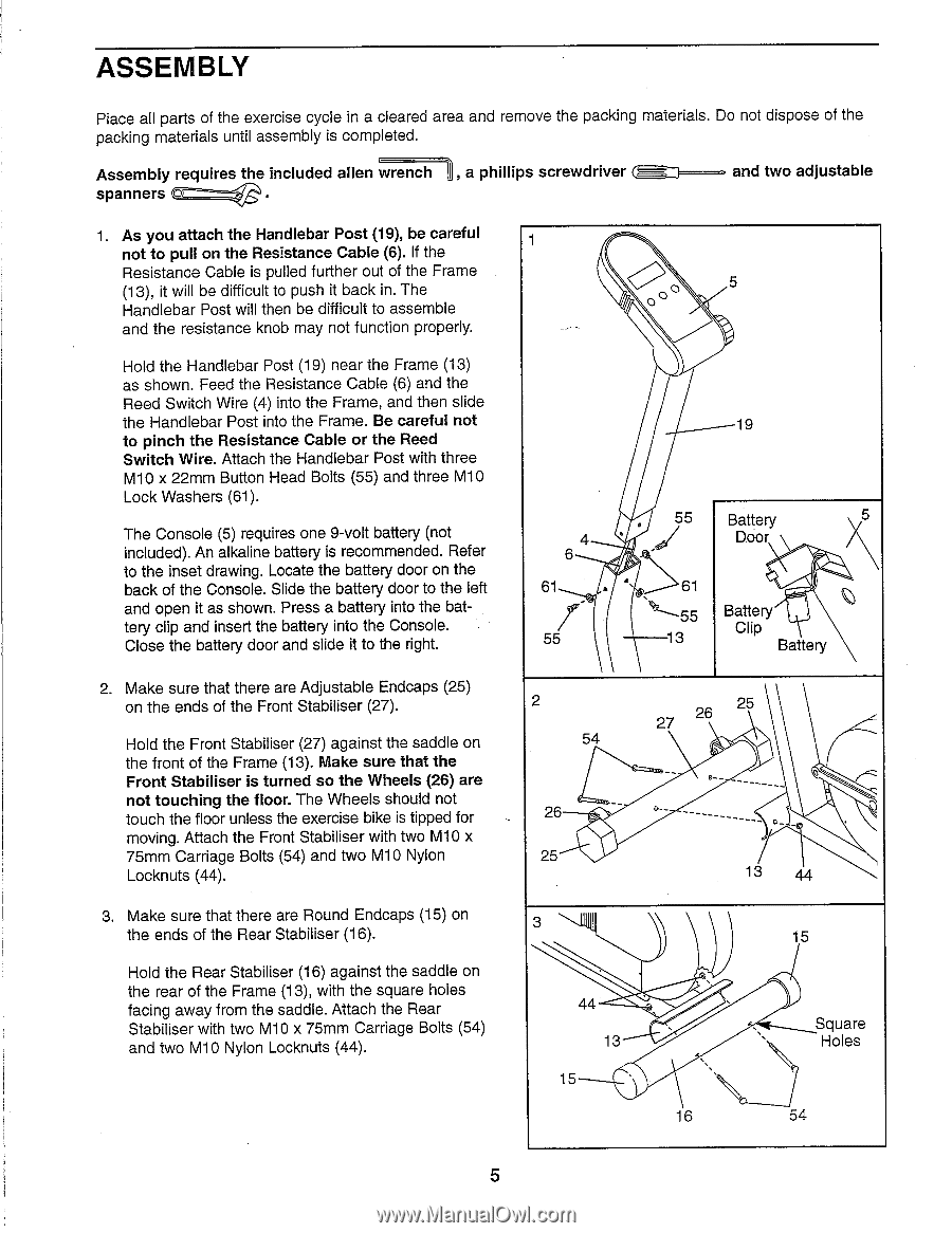
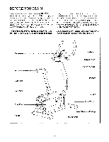
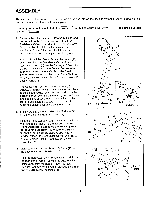
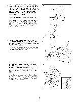
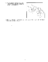
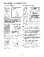
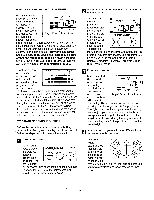
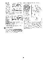
ASSEMBLY Place all parts of the exercise cycle in a cleared area and remove the packing materials. Do not dispose of the packing materials until assembly is completed. Assembly requires the included alien wrench , a phillips screwdriver spanners 0 and two adjustable 1. As you attach the Handlebar Post (19), be careful not to pull on the Resistance Cable (6). If the Resistance Cable is pulled further out of the Frame (13), it will be difficult to push it back in. The Handlebar Post will then be difficult to assemble and the resistance knob may not function properly. Hold the Handlebar Post (19) near the Frame (13) as shown. Feed the Resistance Cable (6) and the Reed Switch Wire (4) into the Frame, and then slide the Handlebar Post into the Frame. Be careful not to pinch the Resistance Cable or the Reed Switch Wire. Attach the Handlebar Post with three M10 x 22mm Button Head Bolts (55) and three M10 Lock Washers (61). The Console (5) requires one 9-volt battery (not included). An alkaline battery is recommended. Refer to the inset drawing. Locate the battery door on the back of the Console. Slide the battery door to the left and open it as shown. Press a battery into the battery clip and insert the battery into the Console. Close the battery door and slide it to the right. 2. Make sure that there are Adjustable Endcaps (25) on the ends of the Front Stabiliser (27). Hold the Front Stabiliser (27) against the saddle on the front of the Frame (13). Make sure that the Front Stabiliser is turned so the Wheels (26) are not touching the floor. The Wheels should not touch the floor unless the exercise bike is tipped for moving. Attach the Front Stabiliser with two M10 x 75mm Carriage Bolts (54) and two M10 Nylon Locknuts (44). 3. Make sure that there are Round Endcaps (15) on the ends of the Rear Stabiliser (16). Hold the Rear Stabiliser (16) against the saddle on the rear of the Frame (13), with the square holes facing away from the saddle. Attach the Rear Stabiliser with two M10 x 75mm Carriage Bolts (54) and two M10 Nylon Locknuts (44). 1 O 0 5 oO 19 6 61 55 2 54 55 Battery 5 Door 61 Battery Clip Battery 27 26 25 26 ___________ 25 13 44 3 15 44 13 15 16 Square Holes 54 5
-
 1
1 -
 2
2 -
 3
3 -
 4
4 -
 5
5 -
 6
6 -
 7
7 -
 8
8 -
 9
9 -
 10
10 -
 11
11 -
12
-
13
-
14
 |
 |