ProForm 940s English Manual - Page 7
Seat Post.
 |
View all ProForm 940s manuals
Add to My Manuals
Save this manual to your list of manuals |
Page 7 highlights
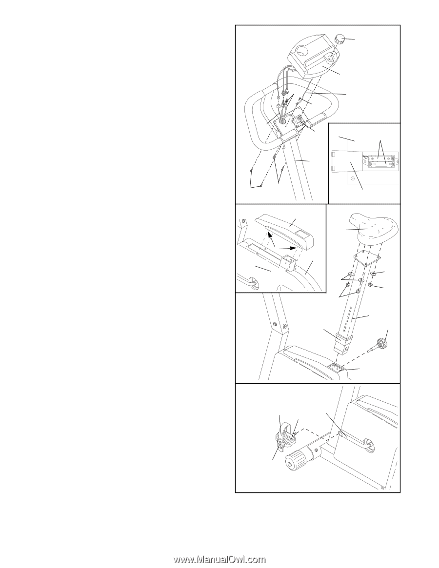
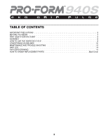
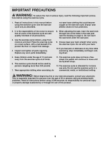
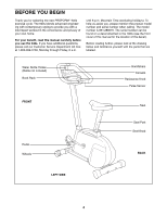
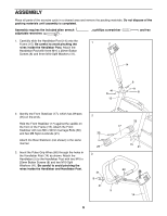
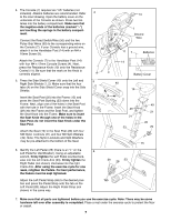
4. The Console (7) requires two ÒAAÓ batteries (not included). Alkaline batteries are recommended. Refer to the inset drawing. Open the battery cover on the underside of the Console as shown. Press two batteries into the battery compartment. Make sure that the negative ends of the batteries (marked ÒÐÓ) are touching the springs in the battery compartment. Connect the Reed Switch/Wire (50) and the two Pulse Grip Wires (60) to the corresponding wires on the Console (7). If your Console has a ground wire, attach it to the Handlebar Post (14) with an M4 x 16mm Screw (9). Attach the Console (7) to the Handlebar Post (14) with four M4 x 12mm Console Screws (4). Next, press the Resistance Knob (10) onto the Resistance Control (11). Be sure that the mark on the Knob is correctly aligned. 5. Press the Side Shield Cover (40) onto the Left and Right Side Shields (1, 2). Make sure that the four tabs (A) on the Side Shield Cover snap into the Side Shields. Insert the Seat Post (20) into the Frame (15) and press the Seat Post Bushing (23) down into the Frame. Next, align one of the holes in the Seat Post with the hole in the Frame. Insert the Seat Knob (29) into the Frame and the Seat Post, and tighten the Seat Knob into the Frame. Make sure to insert the Seat Knob through one of the holes in the Seat Post; do not insert the Seat Knob under the Seat Post. Attach the Seat (19) to the Seat Post (20) with four M8 Nylon Locknuts (21) and four M8 Split Washers (49). Note: The Nylon Locknuts and Split Washers may be pre-attached to the bottom of the Seat. 6. Identify the Left Pedal (28) (there is an ÒLÓ on the Left Pedal for identification). Using an adjustable wrench, firmly tighten the Left Pedal counterclockwise into the left Crank Arm (33). Firmly tighten the Right Pedal (not shown) clockwise into the right Crank Arm. After using the exercise cycle for one week, retighten the Pedals. For best performance, the Pedals must be kept tightened. Adjust the Left Pedal Strap (59) to the desired position and press the Pedal Strap onto the tab on the Left Pedal (28). Adjust the Right Pedal Strap (not shown) in the same way. 4 10 60 9 7 Ground Wire 50 11 7 Batteries 14 4 5 1 4 Battery Cover 40 19 A 2 49 21 23 49 21 20 29 15 6 59 33 28 Tab 7. Make sure that all parts are tightened before you use the exercise cycle. Note: There may be some hardware left over after assembly is completed. Place a mat under the exercise cycle to protect the floor or carpet. 7
-
 1
1 -
 2
2 -
 3
3 -
 4
4 -
 5
5 -
 6
6 -
 7
7 -
 8
8 -
 9
9 -
 10
10 -
 11
11 -
 12
12 -
13
-
14
-
15
-
16
 |
 |