ProForm 980 Audio Trainer Treadmill English Manual - Page 10
Aged When You Turn On The Power.
 |
View all ProForm 980 Audio Trainer Treadmill manuals
Add to My Manuals
Save this manual to your list of manuals |
Page 10 highlights
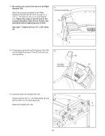
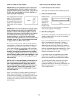
9. Slide the two Handrail Caps (80) onto the lower ends of the Left Handrail (77) and the Right Handrail (78) as shown. Attach the Handrails (77, 78) to the Uprights (81, 83) with two #8 x 3/4" Screws (1), four 5/16" x 2 1/2" Patch Bolts (5), and four 5/16" Star Washers (11). 9 5 11 77 Orient the Handrail Caps (80) as shown. Slide the Handrail Caps against the Uprights (81, 83). Firmly tighten the four 5/16" x 2 1/2" Patch Bolts 80 (5). 1 5 81 78 11 83 80 1 10. Have a second person hold the console assembly near the Right Handrail (78). Connect the Wire Harness (84) to the console wire. See the inset drawing. The connectors should slide together easily and snap into place. If they do not, turn one connector and try again. IF THE CONNECTORS ARE NOT CONNECTED PROPERLY, THE CONSOLE MAY BE DAMAGED WHEN YOU TURN ON THE POWER. Next, remove the wire tie from the Wire Harness. Insert the connectors and the excess wire into the Right Handrail. Set the console assembly on the Right Handrail (78) and the Left Handrail (not shown). Be careful not to pinch the wires. 10 Console Assembly Console Wire 78 84 Wire Tie Console Wire 84 10
-
 1
1 -
2
-
3
-
4
-
 5
5 -
 6
6 -
 7
7 -
 8
8 -
 9
9 -
 10
10 -
 11
11 -
 12
12 -
 13
13 -
 14
14 -
 15
15 -
16
-
17
-
18
-
19
-
20
-
21
-
22
-
23
-
24
-
25
-
26
-
27
-
28
-
29
-
30
-
31
-
32
 |
 |
