ProForm 980 Audio Trainer Treadmill English Manual - Page 12
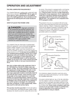
Lower the Frame 51 see HOW TO LOWER
 |
View all ProForm 980 Audio Trainer Treadmill manuals
Add to My Manuals
Save this manual to your list of manuals |
Page 12 highlights
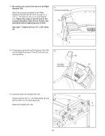
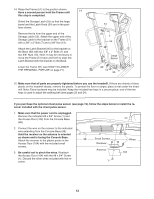
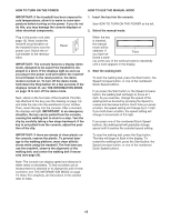
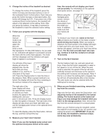
14. Raise the Frame (51) to the position shown. Have a second person hold the Frame until 14 this step is completed. Orient the Storage Latch (55) so that the large barrel and the Latch Knob (54) are in the positions shown. Remove the tie from the upper end of the Storage Latch (55). Attach the upper end of the Storage Latch to the bracket on the Frame (51) with a 3/8" x 2" Bolt (7) and a 3/8" Nut (13). Attach the Latch Bracket (95) to the bracket on the Base (90) with two 3/8" x 2" Bolts (7) and two 3/8" Nuts (13). Note: It may be necessary to move the Frame (51) back and forth to align the Latch Bracket with the bracket on the Base. Lower the Frame (51) (see HOW TO LOWER THE TREADMILL FOR USE on page 21). 51 13 7 55 54 Large Barrel 90 13 95 7 15. Make sure that all parts are properly tightened before you use the treadmill. If there are sheets of clear plastic on the treadmill decals, remove the plastic. To protect the floor or carpet, place a mat under the treadmill. Note: Extra hardware may be included. Keep the included hex keys in a secure place; one of the hex keys is used to adjust the walking belt (see pages 23 and 24). If you purchase the optional chest pulse sensor (see page 19), follow the steps below to install the receiver included with the chest pulse sensor. 1. Make sure that the power cord is unplugged. Remove the indicated #8 x 3/4" Screw (1) and the Access Door (104) from the Console Base (98). 2. Connect the wire on the receiver to the indicated wire extending from the Console Base (98). Hold the receiver so the antenna is oriented as shown and is facing the Console Base. Attach the receiver to the plastic posts on the Access Door (104) with the included small screws. 3. Be careful not to pinch the wires. Reattach the Access Door (104) with the #8 x 3/4" Screw (1). Discard the other wires included with the receiver. 98 Small Screws Receiver Antenna 1 Wires 104 12
-
 1
1 -
2
-
3
-
4
-
5
-
6
-
 7
7 -
 8
8 -
 9
9 -
 10
10 -
 11
11 -
 12
12 -
 13
13 -
 14
14 -
 15
15 -
 16
16 -
 17
17 -
18
-
19
-
20
-
21
-
22
-
23
-
24
-
25
-
26
-
27
-
28
-
29
-
30
-
31
-
32
 |
 |
