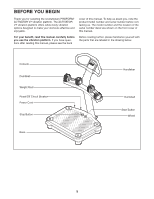
ProForm Activator V7 English Manual - Page 10
Attach the Handlebar 39 to the Upper Upright
 |
View all ProForm Activator V7 manuals
Add to My Manuals
Save this manual to your list of manuals |
Page 10 highlights
8. Tip: Be careful not to pinch the wires during 8 this step. Attach the Upper Upright (36) to the Lower Upright (1) with four M10 x 20mm Patch Screws (28) and four M10 Split Washers (38). See step 5. Tighten the eight M5 x 38mm Screws (40). 36 38 28 28 38 1 9. Tip: Orient the Handlebar (39) so that the sticker with an "R" is in the location shown. 9 Attach the Handlebar (39) to the Upper Upright (36) with two M10 x 62mm Patch Screws (37) and two M10 Split Washers (38). 37 39 38 36 "R" 10. Remove the four M4 x 12mm Self-tapping 10 Screws (27) from the back of the Console (3). Set the Self-tapping Screws aside until step 13. 3 27 27 10
-
 1
1 -
2
-
3
-
4
-
 5
5 -
 6
6 -
 7
7 -
 8
8 -
 9
9 -
 10
10 -
 11
11 -
 12
12 -
 13
13 -
 14
14 -
 15
15 -
16
-
17
-
18
-
19
-
20
 |
 |
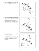
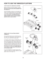
8.
Tip: Be careful not to pinch the wires during
this step.
Attach the Upper Upright (36) to the Lower
Upright (1) with four M10 x 20mm Patch Screws
(28) and four M10 Split Washers (38).
See step 5. Tighten the eight M5 x 38mm
Screws (40).
8
28
1
28
38
38
36
10
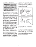
9.
Tip: Orient the Handlebar (39) so that the
sticker with an “R” is in the location shown.
Attach the Handlebar (39) to the Upper Upright
(36) with two M10 x 62mm Patch Screws (37)
and two M10 Split Washers (38).
9
37
38
39
“R”
36
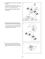
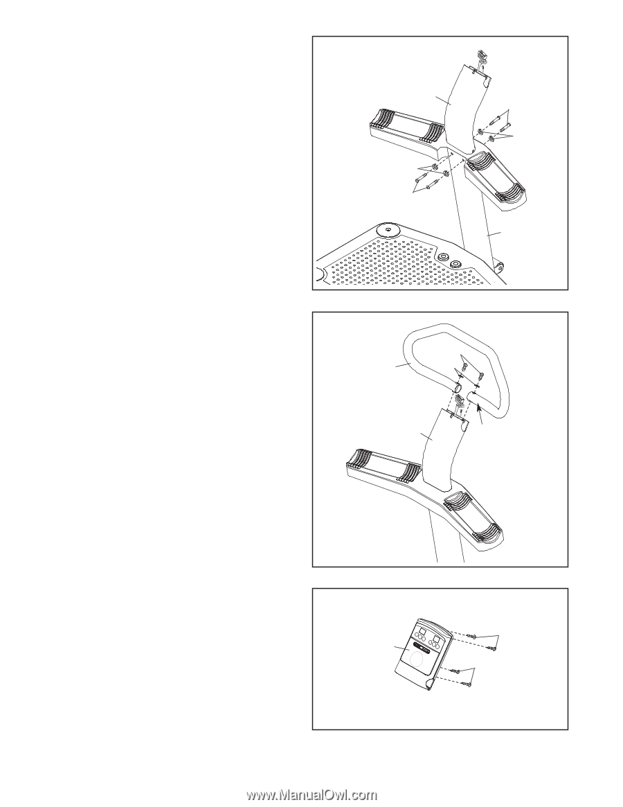
10. Remove the four M4 x 12mm Self-tapping
Screws (27) from the back of the Console (3).
Set the Self-tapping Screws aside until step
13.
10
27
27
3