Pyle AZPLCMTR74 User Manual - Page 2
Plcmtr
 |
View all Pyle AZPLCMTR74 manuals
Add to My Manuals
Save this manual to your list of manuals |
Page 2 highlights
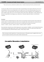
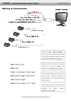
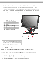
PLCMTR ‐ Commercial Grade Camera System www.pyleaudio.com Please read instructions carefully before installation and use. Installation should be performed by a professional installer. To ensure your safety, the driver should not watch videos or operate features on the monitor while driving. There are no serviceable parts in this unit, do not disassemble or try to repair this unit. If the unit malfunctions please return to your vendor or send to a Pyle repair facility. Please observe and obey the local laws and regulations when installing the unit. Upon Installation, please make sure as to not to interfere with any of the vehicle's safety features, wiring, components, etc. We are not responsible for any damages, injury, malfunctions or otherwise noted due to faulty or non‐professional installation. Connection Connect the camera's threaded locking 4‐pin cable connectors into the female receiving connection of the included 4‐pin extension cables. The extension cables then connect to your compatible video monitors with 4‐pin receiving connectors. The threaded locking cable connectors of the camera serve to provide power and video for all cameras. (camera 1 ‐ channel 1, camera 2 ‐ channel 2, camera 3 ‐ channel 3, camera 4 ‐ channel 4) Please remember to disconnect your vehicle's battery prior to any connection / installation. Use the included wiring harness to provide power and video signals to your monitor. There are colored wires to assist in the video camera system setup. See the wiring diagram for connections between cameras, monitor and your vehicle When turning the vehicle's ignition key or turning to the accessory or ON position, power is supplied to the camera system through the control box and the monitor will be in stand‐by mode.
-
 1
1 -
 2
2 -
 3
3 -
 4
4 -
 5
5 -
 6
6
 |
 |
