Pyle PLE520P PLE520P Manual 1 - Page 10
wiring tips, mounting
 |
View all Pyle PLE520P manuals
Add to My Manuals
Save this manual to your list of manuals |
Page 10 highlights
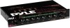
mounting and installation ple730r ple520p mounting Please take the time to install your new Pyle Signal Processor securely, according to this diagram, using the hardware provided. 4 x 6 mm machine screw (4) dashboard Signal Processor enclosure This Half-DIN size unit can also be installed in the dash adjacent to the head unit, provided that there is a slot available. wiring tips When making electrical connections to your amplifier, please observe the following: Mounting Bracket 4 x 12 mm self-tapping screw (2) 4 mm spring washer (2) 4 mm plain washer (2) Connect 12V DC from a constant battery source to a +12V slip-on spade terminal and install a one (1) amp fuse in line. Connect the signal processor's GROUND to a good chassis ground, near where the unit is mounted, or to the case of the head unit. Connect the signal processor's REMOTE TURN-ON lead to the remote turn-on lead out of the head unit, and install a 1/2 amp fuse in line. (A relay should be used if turning on more than one component, such as EQ's, crossovers or amplifiers.) Connect stereo RCA cables from the head's left and right front outputs to the left and right inputs of the signal processor. Connect stereo RCA cables from the left and right outputs, (and low, mid and high outputs if applicable), of the signal processor to the left and right inputs of your amplifier(s) or additional signal processor(s). Turn the unit on, and adjust the input gain on the signal processor to match the output of the head unit (1/2, or at center position, is about 1 V). Be careful not to overdrive the input of your amplifier(s) or signal processor(s). Adjust each of the crossover or equalizer controls to achieve the desired sound characteristics. 8
-
 1
1 -
2
-
3
-
4
-
 5
5 -
 6
6 -
 7
7 -
 8
8 -
 9
9 -
 10
10 -
 11
11 -
 12
12 -
 13
13 -
 14
14 -
 15
15 -
16
 |
 |
