Pyle PWD701 User Guide - Page 5
Installation Instructions
 |
View all Pyle PWD701 manuals
Add to My Manuals
Save this manual to your list of manuals |
Page 5 highlights
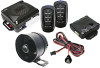
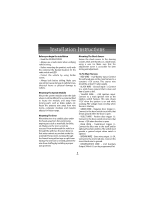
Installation Instructions Before you begin the installation • Read the INSTRUCTIONS! • Always use a multi-meter when verifying vehicle wiring. • Before mounting the product, verify with the customer the desired location for the valet switch and LED. • Protect the vehicle by using fender covers. • Always look before drilling. Make sure you will not cause damage to vehicle hoses, electrical looms or physical damage to vehicle. Mounting The System Module Mount the system module under the dash where it will be difficult for a potential thief to locate the module, and away from moving parts such as brake pedals, etc. Route the antenna wire away from wire looms, computer modules and metallic objects for better range. Mounting The Siren Mount the siren in a suitable place under the hood, away from hot and moving engine parts such as manifolds, fan belts, etc. Make sure the siren cannot be accessed from underneath the vehicle or through the grill. Face the siren down so that water cannot accumulate inside the siren bell. Protect wires running through the firewall using either tape or split loom tubing. If a new hole is needed, protect the wire from chaffing by installing a proper size grommet. Mounting The Shock Sensor Secure the shock sensor to the steering column, thick wire harness or a dash brace, using a wire tie. Make sure that the adjustment screw is accessible for later testing and adjustment. 12-Pin Main Harness: • RED WIRE - +12V Battery input. Connect the red fused wire on the main harness to a constant +12V source. This source wire should be at least 15 amp supply. • BLACK WIRE - Ground input (-). Connect to a solid chassis ground that is clean and free of paint or dirt. • YELLOW WIRE - +12V Ignition input. Connect to a main ignition wire at the ignition switch harness. This wire shows +12V when the ignition is on and while cranking. The voltage must not drop when the car is starting. • GREEN WIRE - Negative door trigger (-). Connect to the door switch circuit wire that shows ground when the door is open. • VIOLET WIRE - Positive door trigger (+). Connect to the door switch circuit wire that shows +12V when the door is open. • BLUE WIRE - Trunk/Hood trigger (-). Connect the Blue wire to the trunk and/or optional hood pin switches.The switch must provide a ground output when switch is opened. • BROWN WIRE - Siren wire output (+) 3A. Connect to the siren's red wire. Connect the siren's black wire to ground. • BROWN/WHITE WIRE - 2nd Auxiliary Output 500mA (-) can be programmed for: 5
-
 1
1 -
 2
2 -
 3
3 -
 4
4 -
 5
5 -
 6
6 -
 7
7 -
 8
8 -
 9
9 -
 10
10
 |
 |