Pyle PWD701 User Guide - Page 6
Plug in Connectors, Entering Programming - wiring
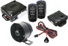 |
View all Pyle PWD701 manuals
Add to My Manuals
Save this manual to your list of manuals |
Page 6 highlights
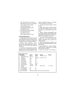
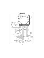
pulsing Horn output, variable pulse output, or 30 second output. Connect to an optional relay to activate these accessories. • BLACK/WHITE WIRE - Dome Light output (-) 500mA. Connect to an optional relay to activate the vehicle's dome light. • ORANGE WIRE - Armed Output (-) 500mA. The ORANGE wire provides a ground when the unit is armed to activate a circuit disable relay or other device (i.e. window control module, etc.). • GRAY WIRE - Auxiliary output (-) 500mA. Connect to a relay for an optional feature such as trunk release, etc. • WHITE WIRE - Parking Light output (+/-) 10A relay. Connect to the vehicle's parking light wire. If the vehicle's parking light circuit exceeds 10 amps a relay is required. For vehicle's with independent left and right parking light circuits, the parking light wires must be connected using diodes to keep the circuits separate. NOTE: Do not connect the WHITE wire to the vehicle's headlight circuit. RED/WHITE WIRE - Parking Light Polarity Selection Input. Connect this wire to +12V Constant for Positive Output on White wire. Connect to Ground for Negative Output on White wire. For Multiplex activated parking light systems, install correct value resistor on this wire. Plug in Connectors 3-Pin Red Door Lock Connector: Plug-in connector port for door lock harness or optional door lock relay module. • BLUE WIRE - unlock output (-) 500mA. • GREEN WIRE - lock output (-) 500mA. 2-Pin White Connector: Plug-in connector port for LED. Mount the LED in an area where it can easily be seen from either the driver or passenger side of the vehicle. 2-Pin Blue Connector: Plug-in connector port for valet switch. Mount switch in an area that is easily accessible from the driver's seat. 4-Pin White Connector: Plug-in connector port for dual stage shock sensor. Entering Programming To enter System Programming: 1. Turn Ignition on. 2. Within 5 seconds press the valet switch 5 times. The siren will emit a long chirp, to indicate entering the program mode. 3. Press the valet switch the number of times equal to the desired feature step. The siren will chirp, and the Led will flash to confirm your selection (example: Step 7 = 1 long chirp, and 2 short chirps. LED will emit 1 long flash, and 2 short flashes.) 4. Within 5 seconds, press the transmitter button corresponding to the desired operation mode for that feature. The siren will chirp, and LED will flash to indicate the setting. One chirp/flash = Button 1 Two chirps/flashes = Button 2 Three chirps/flashes = Button 3 Four chirps/flashes = Button 4 Turn off Ignition to save changes. Siren will chirp 3 times. Parking Lights will flash 3 times Complete Default Reset This procedure will reset all Programmable Features to factory default settings. 1. Enter System Programming. 2. Press valet switch 16 times. Siren will 6
-
 1
1 -
 2
2 -
 3
3 -
 4
4 -
 5
5 -
 6
6 -
 7
7 -
 8
8 -
 9
9 -
 10
10
 |
 |