Pyle SLFTRD20 Instruction Manual - Page 7
Incline Adjustment
 |
View all Pyle SLFTRD20 manuals
Add to My Manuals
Save this manual to your list of manuals |
Page 7 highlights
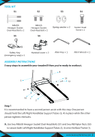
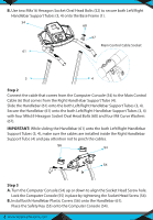
Rear Right Cover Rear Left Cover Frame Step 4 A. Remove one Flat Head Phillips Screw from both sides of the Frame. Attach the Rear Left Cover onto the left side of the Frame. Align the holes and secure the Rear Left Cover using the one Flat Head Phillips Screws , that were previously removed by Allen Wrench. B. Align the holes and secure the Rear Right Cover using the one Flat Head Phillips Screws that were previously removed by Allen Wrench. Incline Adjuster Lock Pin INCLINE ADJUSTMENT There are 3 incline angles that the Incline Adjuster can be set to. Place one hand on the rear end of the main frame, then lift the rear end of the main frame up and use the other hand to remove the Lock Pin. Adjust the Incline Adjuster to the desired position and insert the Lock Pin into the holes on the main frame and Incline Adjuster to lock the Incline Adjuster in place. www.SereneLifeHome.com 7
-
 1
1 -
 2
2 -
 3
3 -
 4
4 -
 5
5 -
 6
6 -
 7
7 -
 8
8 -
 9
9 -
 10
10 -
 11
11 -
 12
12 -
13
-
14
-
15
-
16
-
17
-
18
 |
 |
